Summary of PIC16F88 LCD TACHOMETER CIRCUIT
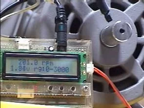
This article describes a PIC16F88-based LCD tachometer circuit that measures RPM using an RPR-220 reflective sensor and outputs an analog voltage proportional to rotation speed via PWM. The system features calibration switches for range adjustment, a hold function to freeze readings, and a test mode for full-scale output verification. It supports multiple RPM ranges from 300 to 60,000 with a display resolution up to 99,999.9 RPM.
Parts used in the PIC16F88 LCD Tachometer Circuit:
- PIC16F88 microcontroller
- LCD display
- RPR-220 reflective sensor
- 940nm infrared LED
- Phototransistor
- HOLD switch
- TEST switch
- A-RANGE switch
- Output filter
PIC16F88Rpm analog voltage output that is, PWM signal so that only the output filter will depend on VDD. While there, press the switch, use the calibration and output voltage range equivalent to the rotation….Electronics Projects, PIC16F88 LCD Tachometer Circuit “microchip projects, microcontroller projects, pic16f88 projects, “
PIC16F88Rpm analog voltage output that is, PWM signal so that only the output filter will depend on VDD. While there, press the switch, use the calibration and output voltage range equivalent to the rotation. 0-6000, for example when a voltage range of 4.8V to press on with this switch. Analog output voltage is 2.4V when you rotate 6000×2.4/4.8 = 3000rpm. ROHM detection sensors are made of reflective sensors RPR-220 was used. 6mm from the tip of the infrared focal point was set at an angle of LED (940nm) is now one of the phototransistor. It looks like some of 630nm light source PIC16F88 HI-TECH PICC software production has been created. CCS-C with a little modification should be transplanted. I am, I have an older version, most (at all) is not being used.
TACHOMETER CIRCUIT SPECIFICATION
Range: 17.9 ~ 99999.9 rpm (or so to about errors 20000rpm)
Sensor input: Voltage values. The reflection of the actual measurement is adjusted for RB0 interrupt edge
Analog output rotation: 8 range, 0 – full-scale :0-VDD (10bitPWM)
Analog output range: 300,500,1000,3000,6000,10000,30000,60000 rpm
HOLD switch: While the press, sensor input, to hold the rotating numeral
TEST switch: While the press, full-scale output voltage analog output
A-RANGE switch: Change the value of full-scale analog output
Source: PIC16F88 LCD TACHOMETER CIRCUIT Tachometer Circuit schematic picmicro source code files: pic16f88-lcd-tachometer-circuit.rar alternative link2
Alternative File Download LINK list (in TXT format): LINKS-25299.zip
- What is the primary function of this project?
The project creates a tachometer circuit using a PIC16F88 microcontroller to measure RPM and provide an analog voltage output. - How does the sensor input work?
The sensor input uses voltage values adjusted for RB0 interrupt edge based on the reflection from the actual measurement. - Can the analog output range be changed?
Yes, the A-RANGE switch allows changing the value of the full-scale analog output among eight specific ranges. - What is the purpose of the HOLD switch?
While pressing the HOLD switch, the sensor input reading is held to freeze the rotating numeral on the display. - How is the TEST switch utilized?
Pressing the TEST switch generates a full-scale output voltage for the analog output. - What type of sensor is used for detection?
ROHM RPR-220 reflective sensors are used, featuring a 940nm infrared LED and a phototransistor. - What software was used to create the project?
The project was created using HI-TECH PICC software, though CCS-C can be transplanted with minor modifications. - What is the maximum measurable RPM range?
The specification lists a range of 17.9 to 99999.9 rpm, though errors may occur around 20000 rpm. - How is the analog output generated?
Analog output rotation is generated as a 10-bit PWM signal ranging from 0 to VDD.