Summary of PIC16F84A + DHT11 Proteus simulation
This article details interfacing the DHT11 (RHT01) temperature and humidity sensor with a PIC16F84A microcontroller using Proteus 8.1 or higher for simulation. It explains the sensor's specifications, including its 3.3-5.5V operation range and measurement capabilities. The text outlines the proprietary one-wire communication protocol, emphasizing precise timing for start signals and data reception. Finally, it describes the 40-bit data structure comprising relative humidity and temperature values along with a checksum.
Parts used in the PIC16F84A and DHT11 Interfacing Project:
- PIC16F84A microcontroller
- DHT11 (RHT01) sensor
- Proteus software version 8.1 or higher
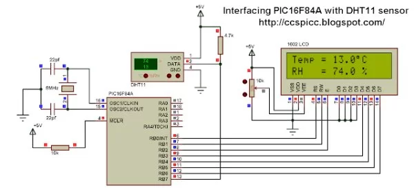
Interfacing PIC16F84A microcontroller with DHT11(RHT01) sensor
This topic shows how to interface DHT11 (RHT01) digital relative humidity and temperature sensor with PIC16F84A microcontroller, and how to simulate this interfacing using Proteus.
Note that for the simulation Proteus version should be 8.1 or higher. With these versions there is no need to install Proteus DHT11 library, it is included with the software, so don’t waste your time searching for dht11 Proteus library or dhtxx.mdf or dht11 module for Proteus, just use Proteus version 8.1 or higher.
About DHT11 (RHT01) relative humidity and temperature sensor:
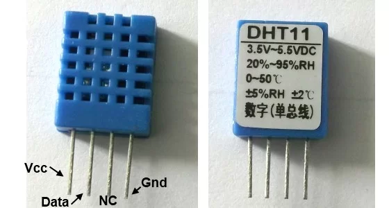
The DHT11 sensor comes in a single row 4-pin package and operates from 3.3 to 5.5V power supply. It can measure temperature from 0-50 °C with an accuracy of ±2°C and relative humidity ranging from 20-90% with an accuracy of ±5%. The sensor provides fully calibrated digital outputs for the two measurements. It has got its own proprietary 1-wire protocol, and therefore, the communication between the sensor and a microcontroller is not possible through a direct interface with any of its peripherals. The protocol must be implemented in the firmware of the MCU with precise timing required by the sensor.
The DHT11 sensor comes in a single row 4-pin package and operates from 3.3 to 5.5V power supply. It can measure temperature from 0-50 °C with an accuracy of ±2°C and relative humidity ranging from 20-90% with an accuracy of ±5%. The sensor provides fully calibrated digital outputs for the two measurements. It has got its own proprietary 1-wire protocol, and therefore, the communication between the sensor and a microcontroller is not possible through a direct interface with any of its peripherals. The protocol must be implemented in the firmware of the MCU with precise timing required by the sensor.
timing diagrams describe the data transfer protocol between a MCU and the DHT11 sensor. The MCU initiates data transmission by issuing a “Start” signal. The MCU pin must be configured as output for this purpose. The MCU first pulls the data line low for at least 18 ms and then pulls it high for next 20-40 us before it releases it. Next, the sensor responds to the MCU “Start“ signal by pulling the line low for 80 us followed by a logic high signal that also lasts for 80 us. Remember that the MCU pin must be configured to input after finishing the “Start“ signal. Once detecting the response signal from the sensor, the MCU should be ready to receive data from the sensor. The sensor then sends 40 bits (5 bytes) of data continuously in the data line. Note that while transmitting bytes, the sensor sends the most significant bit first.

Data format: 8bit integral RH data + 8bit decimal RH data + 8bit integral T data + 8bit decimal T data + 8bit check sum. If the data transmission is right, the check-sum should be the last 8bit of “8bit integral RH data + 8bit decimal RH data + 8bit integral T data + 8bit decimal T data”.
Data consists of decimal and integral parts. A complete data transmission is 40bit, and the sensor sends higher data bit first.
Data format: 8bit integral RH data + 8bit decimal RH data + 8bit integral T data + 8bit decimal T data + 8bit check sum. If the data transmission is right, the check-sum should be the last 8bit of “8bit integral RH data + 8bit decimal RH data + 8bit integral T data + 8bit decimal T data”.
The DHT11 is a digital sensor so it sends 1’s and 0’s, but it is very important to know how it sends the digital data. The figure below shows how the sensor sends its information:
Read more: PIC16F84A + DHT11 Proteus simulation
- What Proteus version is required for this simulation?
Proteus version 8.1 or higher is required as it includes the DHT11 library. - Can I use an external library for the DHT11 sensor in Proteus?
No, you do not need to install any external library if using Proteus 8.1 or higher. - What is the operating voltage range of the DHT11 sensor?
The sensor operates from a 3.3 to 5.5V power supply. - How does the MCU initiate data transmission with the DHT11?
The MCU initiates transmission by pulling the data line low for at least 18 ms and then high for 20-40 us. - What happens after the MCU sends the Start signal?
The sensor responds by pulling the line low for 80 us followed by a logic high signal lasting 80 us. - How many bits of data does the sensor send continuously?
The sensor sends 40 bits, which equals 5 bytes of data. - In what order does the sensor transmit the data bits?
The sensor sends the most significant bit first during transmission. - What components make up the complete 40-bit data transmission?
The data consists of 8bit integral RH, 8bit decimal RH, 8bit integral T, 8bit decimal T, and an 8bit check sum.