Summary of PIC16F84 LCD DISPLAY LC METER
This project describes a PIC16F84-based LC Meter with an LCD display housed in a custom box. The builder emphasizes careful box preparation, including pasting a template, cutting the front panel, and securing it with four M3 screws. Key technical details include using a 12V DC power jack, a terminal block for testing connections, and specific jumper settings for the LCD, frequency test, and backlight. The article also notes a correction regarding relay diode orientation to ensure proper circuit protection.
Parts used in the PIC16F84 LCD Display LC Meter:
- PIC16F84 Microcontroller
- 16 × 1 LCD Display
- Relay with internal diode
- Protection Diode
- 12 Volt DC Jack (interior positive, outer ground)
- Testing Terminal Block
- Jumper J1 (for LCD connection)
- Jumper J2 (for Frequency test)
- Jumper J3 (for Background light)
- Four M3 screws and nuts
PIC16F84 LCD Display LC Meter circuit Box front waisted measure be careful when buying the box to cut the picture box paste it on top and falçata or drawing a knife then stop in the box bourdu to keep… Electronics Projects, PIC16F84 LCD Display LC Meter “microchip projects, microcontroller projects, pic16f84 projects,
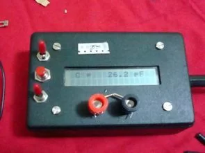
PIC16F84 LCD Display LC Meter circuit Box front waisted measure be careful when buying the box to cut the picture box paste it on top and falçata or drawing a knife then stop in the box bourdu to keep the four M3 screws and nuts, use Bordt USING the reader relays internal diode line is I’m a little late, I realized I did board relay leg reverse came first problem was that but in the scheme and BoardTM fix but I still protection diode I used the relay of different uses for kaldırmadım.pow source 12 Volt DC Jack (interior +) (outer portion of the Gnd)
I’ve used for testing terminal born request you make the connection, but the cable is too long to keep going to use.
Also I do jumper in a description:
J1: 16 × 1 LCD for those who want to use
J2: Frequency test
J3: Background light
CIRCUIT DIAGRAM, BOX SIZE, BOX SECTION, BOX CUT METHOD
Source: PIC16F84 LCD DISPLAY LC METER
- How should I prepare the front of the project box?
Paste the picture on top, use a file or knife to cut, and stop at the box border to keep the area clean. - What hardware is needed to secure the box front?
You need four M3 screws and nuts to hold the front panel in place. - Did the author encounter issues with the relay diode?
Yes, the author initially connected the relay leg in reverse but fixed the problem by correcting the orientation in the scheme and board. - What type of power source does this meter require?
The circuit uses a 12 Volt DC Jack where the interior is positive and the outer portion is ground. - What is the purpose of jumper J1?
Jumper J1 is used for connecting the 16 × 1 LCD display. - What function does jumper J2 serve?
Jumper J2 is designated for the frequency test. - Which jumper controls the background light?
Jumper J3 is used to control the background light. - Why did the author mention using a terminal block?
The author used a terminal block for making test connections because the cable was too long to keep going directly.