Summary of PIC12F675 ADC code and Proteus simulation
This article provides C code (MPLAB with HI-TECH C) and a Proteus simulation for using the 10-bit ADC of a PIC12F675 to display conversion results on an LCD. It explains channel selection (AN0–AN3), VREF = VDD (VCFG = 0), usage of InitADC(channel) and GetADCValue(channel) functions, and shows a demo reading AN3 every 0.5s. Code and simulation download link available.
Parts used in the PIC12F675 ADC project:
- PIC12F675 microcontroller
- LCD module
- Variable resistor (potentiometer)
- 5V power supply (VDD)
- Wiring / breadboard or PCB for connections
- MPLAB IDE with HI-TECH C compiler (for compiling code)
- Proteus software (for simulation)
This post provides the ADC code using PIC12F675 microcontroller. This code is written in C language using MPLAB with HI-TECH C compiler. You can download this code from the ‘Downloads‘ section at the bottom of this page.
It is assumed that you know how to interface LCD with PIC12F675 microcontroller. If you don’t then please read this page first, before proceeding with this article.
The result of simulating the code in Proteus is shown below.
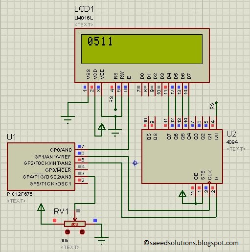
In the above figure, pin3(AN3) of PIC12F675 is being used as ADC input pin[1]. The result of ADC conversion is shown on the LCD screen. If you attach pin3 of PIC12F675 to ground, then a value of 0000 will be displayed on the LCD screen and if you attach pin3 with 5v power supply, then a value of 1023 will be displayed on the LCD screen. In other words, ADC resolution is 10bits and value of ADC result varies from 0(0v) to 1023(5v). Because there is a variable resistor of 50% value attached on pin3 of PIC12F675 in Figure1, that is why it has 2.5v on it. As a result, a value of 511(Half of 1023) is being displayed on the LCD.
Consider the figure shown below[2].
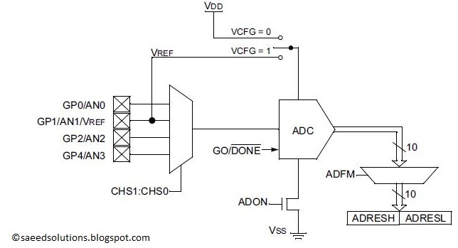
This figure shows that at a single time, only one ADC channel can be selected as an input channel for ADC conversion. We can select AN0 or AN1 or AN2 or AN3 channel depending upon CHS1:CHS0 bits. In the code I have given a simple channel selection method (Explained below in the code section). I have selected VCFG to be zero, hence VREF is equal to VDD (Of-course you can change this if you want).
Code
The code used to initialize ADC input channels is shown below.
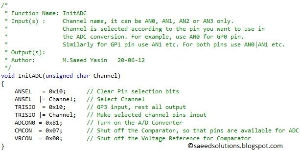
InitADC() function should be called in the start of main function to initialize ADC input channels. You will need to pass an input argument to InitADC() function. For example, if you want to initialize ADC on AN0(pin7) channel, then write InitADC(AN0); in your code. To initialize multiple channels for example, AN1 and AN2 you can write InitADC(AN1|AN2); in your code etc.
The function used to read ADC value from input pin is shown below.
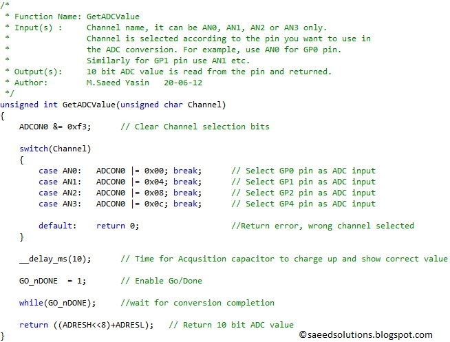
To read ADC value from AN0 channel, you can write GetADCValue(AN0); in your code. Similarly, you can read ADC value from all other channels as well. You can read ADC value only from one channel at a time. GetADCValue() function returns the 10bit ADC value.
The main function code is shown below.
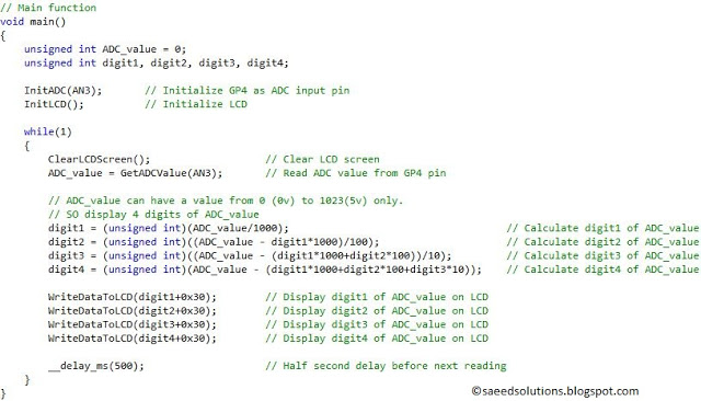
In the main function, ADC is initialized on pin3(AN3), you can see in Figure1 that ADC input is attached on this pin. After ADC, LCD is initialized using InitLCD()function. After that, in the while loop code reads ADC value from AN3 channel after every half second and converts this integer value into 4 digits. And those digits are displayed on the LCD screen.
In this way, after every half second new ADC value is updated on the LCD screen. You can use this ADC code library in your projects. You can leave your comments in the comment section below.
Notes and References
[1] Besides pin3(AN3), you can select pin7(AN0) or pin6(AN1) or pin5(AN2) as ADC input pin.
[2] This figure is taken from PIC12F675 datasheet, ADC chapter.
Downloads
ADC code using PIC12F675 was compiled in MPLAB v8.85 with HI-TECH C v9.83 compiler and simulation was made in Proteus v7.10. To download code and Proteus simulation click here.
Further Reading Suggestions
You may also like,
Source : PIC12F675 ADC code and Proteus simulation
- How is ADC initialized in the provided code?
Call InitADC with the desired channel argument like InitADC(AN3) to initialize ADC on that channel. - How do you read an ADC value from a channel?
Use GetADCValue with the channel argument, for example GetADCValue(AN0); it returns the 10bit ADC value. - What ADC resolution does PIC12F675 provide in this project?
The ADC resolution is 10 bits, producing values from 0 to 1023 corresponding to 0V to 5V. - Which pins can be used as ADC inputs on PIC12F675?
AN0 on pin7, AN1 on pin6, AN2 on pin5, and AN3 on pin3 can be used as ADC inputs. - What reference voltage is used for ADC in the code?
VCFG is set to zero so VREF is equal to VDD (5V) in the provided code. - Can multiple ADC channels be initialized at once?
Yes, you can pass a bitwise OR of channels to InitADC, for example InitADC(AN1|AN2). - Can GetADCValue read multiple channels at the same time?
No, GetADCValue reads ADC value from only one selected channel at a time. - How often does the example update the LCD with ADC values?
The example reads the ADC and updates the LCD every half second.