Summary of PIC12F629 WATER LEVEL CONTROL CIRCUIT PROTON BASIC
This article describes a water level control system using a PIC12F629 microcontroller to manage tank filling and well pumping. The circuit utilizes three plastic-sheathed probe rods to detect water levels, triggering transistors and 4N25 optocouplers for safe logic processing. It includes error detection for fill failures and optional manual reset switches, with software written in Proton Basic.
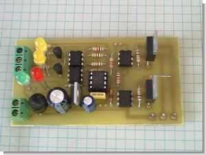
Parts used in the PIC12F629 Water Level Control Circuit:
- PIC12F629 microcontroller
- Three plastic-sheathed conductor rod probes (A, B, and C)
- Transistors
- 4N25 optocoupler
- Water pump motor
- ERROR LED
- A and B status LEDs
- ON-OFF switch
- Proton Basic compiler
This half of the water tank water level control or operate the wells. To measure the water level in the tank is used three level probe. These plastic-sheathed conductor rods. Probe to determine the level of the top of… Electronics Projects, PIC12F629 Water Level Control Circuit Proton Basic “microchip projects, microcontroller projects, picbasic pro examples,
This half of the water tank water level control or operate the wells. To measure the water level in the tank is used three level probe. These plastic-sheathed conductor rods. Probe to determine the level of the top of the water. B probe would be the lowest level of the water determines the C probe on the bottom of the tank or the tank is metal probe to be connected to the outer frame. Its task is that of water into the electric current amount. Thanks to this current probe connected to other transistors trigger. Depending on the transistor optocouplers logic sends a command to the PIC pins. Of optocoupler (4N25) intended use of the water in the tank for any reason, is a high-voltage electrical leakage to prevent the deterioration of PICs.
When you first run the circuit, the PIC controls the A and B probes, respectively, and one of them almost immediately filling tank engine runs idle. GP3 pin PICs switch connected to the water pump motor controls. Tank during filling pump motor does not work. When the water level reaches the probe filling the engine stops and the GP3 engine is no longer connected to the pump, from this moment you can use with the key. During pumping water if the water level falls below the B probe and tank filling pump motor stops the engine starts to run until the possible taki probe.
WATER LEVEL CONTROL PROJECT SCHEMATIC
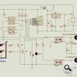
If you fill the water tank filling process gerşekleşmess ie the water level when the engine first tries to probe B in 1 minute ulaşmass water refilling engine automatically stops and the ERROR LED will start flashing. From this moment the water level to B before reaching the pump and filling the engine work. In the ON-OFF switch to reset the circuit used.
In addition, any of the optional circuit can remove the engine. If you use the example circuit in the well water here is not the filling process can only connect the pump motor. B is thereby reduced below the water level in the well pump when the engine is stopped or until the water level again function. When the water runs clear and full again, even though the pump motor will not start again. engine, with the key must be turned off and on again.
A ‘and B’ and B LEDs indicate the status of the probe.
PIC software is prepared with basic proton. PBP version of the software is further optionally and PIC12F629, PIC12F675 contains versiyonları.
Source files in the printed circuit board and Proteus 7.5 SP3 is available in simülasyonları. If you are using Proteus version does not comply with it within the folder “section isis” and “ARES region” Save whether you import files.
CIRCUIT is tested.
PIC12F629 Water Level Control Circuit Proton Basic Project files ( isis, ares, pic-basic, proton ) and the materials used in the circuit datasheet files:
FILE DOWNLOAD LINK LIST (in TXT format): LINKS-6725.zip
Source: PIC12F629 WATER LEVEL CONTROL CIRCUIT PROTON BASIC
- How does the system measure the water level?
The system uses three plastic-sheathed conductor rods to determine the top, lowest, and bottom water levels. - What is the function of the 4N25 optocoupler?
The 4N25 optocoupler prevents high-voltage electrical leakage from deteriorating the PIC microcontroller. - When does the pump motor stop during the filling process?
The engine stops when the water level reaches the A probe, disconnecting the GP3 pin from the pump. - What happens if the water level falls below probe B while pumping?
The tank filling pump motor stops, and the engine starts running until the water level reaches probe C. - How does the system handle a failed refill attempt?
If the water level does not reach probe B within one minute, the refilling engine stops and the ERROR LED flashes. - How can the user reset the circuit after an error?
The circuit is reset using the ON-OFF switch located on the board. - Can this circuit be used for a well without a tank?
Yes, by removing the tank filling component, the circuit connects only to the pump motor for well operation. - Which software was used to prepare the PIC software?
The PIC software was prepared using Proton Basic, supporting versions like PBP.