Summary of PIC Microcontrollers – Programming in C
This chapter gives practical basics for using microcontrollers: power, reset, clock, and common peripherals. It explains using a 5V supply with an LM7805, MCLR reset with pull-up resistor and button, oscillator modes (LP, XT, HS, RC, external), and additions like switches (debounce methods), relays with flyback diode, LEDs and 7-segment displays (current limiting, multiplexing, masking), and optocouplers for galvanic isolation.
Parts used in the Microcontroller Basics project:
- PIC16F887 microcontroller
- 5V DC power supply
- LM7805 three-terminal positive regulator
- 10K resistor (pull-up for MCLR)
- Push-button for reset (MCLR to GND)
- Quartz crystal
- C1 and C2 capacitors (crystal load capacitors)
- Ceramic resonator
- RC network components (resistor and capacitor for RC oscillator)
- External oscillator (clock source)
- Resistors (general use and current limiting)
- Transistors (drivers for multiplexing/display)
- LED diodes
- 7-segment LED display (common anode or common cathode)
- Multiplexing driver transistors
- Relay (with coil)
- Inverted polarized diode (flyback diode for relay)
- Optocoupler (with phototransistor output)
- SPDT switch (for RS flip-flop hardware debounce)
The purpose of this chapter is to provide basic information that one needs to know in order to be able to use microcontrollers successfully in practice. This chapter, therefore, doesn’t contain any super interesting program or device schematic with amazing solutions. Instead, the following examples are better proof that program writing is neither a privilege nor a talent issue, but the ability of simply putting puzzle pieces together using directives. Rest assured that design and development of devices mainly consists of the ‘test-correct-repeat’ work. Of course, the more you are in it, the more complicated it gets since the puzzle pieces are put together by both children and first-class architects…
BASIC CONNECTING
In order to enable the microcontroller to operate properly it is necessary to provide:
- Power Supply;
- Reset Signal; and
- Clock Signal.
As seen in figure above, it is about simple circuits, but it does not have to be always like that. If the target device is used for controlling expensive machines or life-support devices, everything gets increasingly complicated! However, this solution is sufficient for the time being…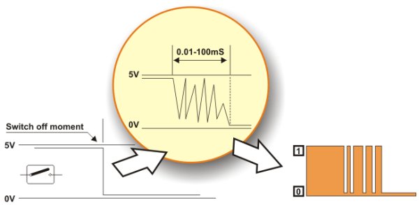
POWER SUPPLY
Even though the PIC16F887 can operate at different supply voltages, why to test ‘Murphy’s low’?! A 5V DC power supply is the most suitable. The circuit, shown on the previous page, uses a cheap integrated three-terminal positive regulator LM7805 and provides high-quality voltage stability and quite enough current to enable the microcontroller and peripheral electronics to operate normally (enough here means 1A).
RESET SIGNAL
In order that the microcontroller can operate properly, a logic one (VCC) must be applied on the reset pin. The push button connecting the reset pin MCLR to GND is not necessary. However, it is almost always provided because it enables the microcontroller to return safely to normal operating conditions if something goes wrong. By pushing this button, 0V is brought to the pin, the microcontroller is reset and the program execution starts from the beginning. A10K resistor is used to allow 0V to be applied to the MCLR pin, via the push button, without shorting the 5VDCrail to earth.
CLOCK SIGNAL
Even though the microcontroller has a built-in oscillator, it cannot operate without external components which stabilize its operation and determine its frequency (operating speed of the microcontroller). Depending on elements in use as well as their frequencies, the oscillator can be run in four different modes:
- LP – Low Power Crystal;
- XT – Crystal / Resonator;
- HS – High speed Crystal / Resonator; and
- RC – Resistor / Capacitor.
Why are these modes so important? Owing to the fact that it is almost impossible to make a stable oscillator which operates over a wide frequency range, the microcontroller must know which crystal is connected so that it can adjust the operation of its internal electronics to it. This is why all programs used for chip loading contain an option for oscillator mode selection. See figure on the left.
Quartz Crystal
When the quartz crystal is used for frequency stabilization, a built-in oscillator operates at a precise frequency which is not affected by changes in temperature and power supply voltage. This frequency is usually labeled on the crysal casing.
Apart from the crystal, capacitors C1 and C2 must also be connected as per schematic below. Their capacitance is not of great importance. Therefore, the values provided in the table below should be considered as a recommendation, not as a strict rule.
Ceramic Resonator
Ceramic resonator is cheaper, but very similar to quartz by its function and the way of operation. This is why schematics illustrating their connection to the microcontroller are identical. However, the capacitor value is slightly different due to different electric features. Refer to the table below.
Such resonators are usually connected to oscillators when it is not necessary to provide extremely precise frequency.
RC Oscillator
If the operating frequency is not of importance then there is no need to use additional expensive components for stabilization. Instead, a simple RC network, as shown in figure below, is sufficient. Since only the input of the local oscillator is used here, the clock signal with the Fosc/4 frequency will appear on the OSC2 pin. This frequency also represents the operating frequency of the microcontroller, i.e. the speed of instruction execution.
External Oscillator
If it is required to synchronize the operation of several microcontrollers or if for some reason it is not possible to use any of the previous schematics, a clock signal may be generated by an external oscillator. Refer to figure below.
Regardless of the fact that the microcontroller is a product of modern technology, it is of no use if not connected to additional components. Simply put, the appearance of voltage on the microcontroller pins means nothing if not used for performing certain operations such as to turn something on/off, shift, display etc.
ADDITIONAL COMPONENTS
This section covers the most commonly used additional components in practice such as resistors, transistors, LED diodes, LED displays, LCD displays and RS232 communication circuits.
SWITCHES AND PUSH-BUTTONS
Switches and push-buttons are probably the simplest devices providing the simplest way of detecting the appearance of a voltage on a microcontroller input pin. Nevertheless, it is not as simple as it seems… The reason for it is a contact bounce.
The contact bounce is a common problem with mechanical switches. When the contacts strike together, their momentum and elasticity act together to cause bounce. The result is a rapidly pulsed electrical current instead of a clean transition from zero to full current. It mostly occurs due to vibrations, slight rough spots and dirt between contacts. This effect is usually unnoticeable when using these components in everyday life because the bounce happens too fast to affect most equipment. However, it causes problems in some analog and logic circuits that respond fast enough to misinterpret on/off pulses as a data stream. Anyway, the whole process doesn’t last long (a few micro or milliseconds), but long enough to be registered by the microcontroller. When only a push-button is used as a counter signal source, errors occur in almost 100% of cases!
This problem may be easily solved by connecting a simple RC circuit to suppress quick voltage changes. Since the bounce period is not defined, the values of components are not precisely determined. In most cases it is recommended to use the values as shown in figure below.
If complete stability is needed then radical measures should be taken. The output of the circuit, shown in figure below (RS flip-flop), will change its logic state only after detecting the first pulse triggered by a contact bounce. This solution is more expensive (SPDT switch), but the problem is definitely solved.
In addition to these hardware solutions, there is also a simple software solution. When the program tests the logic state of an input pin and detects a change, the check should be done one more time after a certain delay. If the program confirms the change, it means that a switch/push button has changed its position. The advantages of such solution are obvious: it is free of charge, effects of contact bounce are eliminated and it can be applied to the poorer quality contacts as well.
RELAY
A relay is an electrical switch that opens and closes under the control of another electrical circuit. It is therefore connected to output pins of the microcontroller and used to turn on/off high-power devices such as motors, transformers, heaters, bulbs, etc. These devices are almost always placed away from the board’s sensitive components. There are various types of relays, but all of them operate in the same way. When current flows through the coil, the relay is operated by an electromagnet to open or close one or more sets of contacts. Similar to optocouplers, there is no galvanic connection (electrical contact) between input and output circuits. Relays usually demand both higher voltage and higher current to start operation, but there are also miniature ones that can be activated by low current directly obtained from a microcontroller pin.
This figure below shows the most commonly used solution.
In order to prevent the appearance of high voltage self-induction, caused by a sudden stop of the current flow through the coil, an inverted polarized diode is connected in parallel to the coil. The purpose of this diode is to ‘cut off’ the voltage peak.
LED DIODES
You probably know all you need to know about LED diodes, but you should also think of the younger generations… Let’s see, how to destroy an LED?! Well…Easily.
Quick Burning
Like any other diode, LEDs have two ends- an anode and a cathode. Connect a diode properly to the power supply voltage and it will happily emit light. Turn the diode upside down and apply the same power supply voltage (even for a moment). It will not emit light – NEVER AGAIN!
Slow Burning
There is a nominal, i.e. maximum current limitation specified for every LED which must not be exceeded. If it happens, the diode will emit more intensive light, but just for a short period of time.
Something to Remember
Similarly, all you need to do is to discard a current limiting resistor shown below. Depending on the power supply voltage, the effects might be spectacular!
LED DISPLAY
Basically, an LED display is nothing more than several LEDs molded in the same plastic case. There are many types of displays and some of them are composed of several dozens built-in diodes which can display different symbols. Nevertheless, the most commonly used display is the 7-segment display. It is composed of 8 LEDs. Seven segments of a digit are arranged as a rectangle for symbol displaying, whereas the additional segment is used for the purpose of displaying decimal point. In order to simplify connection, anodes or cathodes of all diodes are connected to the common pin so that there are common anode displays and common cathode displays, respectively. Segments are marked with the letters from a to g, plus dp, as shown in figure below. When connecting, each diode is treated separately, which means that each must have its own current limiting resistor.
Here are a few important things that you should pay attention to when buying LED displays:
- As mentioned, depending on whether anodes or cathodes are connected to the common pin, there are common anode displays and common cathode displays. As for their appearance, there is no difference between these displays at all so it is recommended to check carefully prior to installing them which one is used.
- Each microcontroller pin has a maximum current limitation it can receive or give. Thus, if several displays are connected to the microcontroller it is recommended to use the so called Low current LEDs using only 2mA for the operation.
- Display segments are usually marked with the letters from a to g, but there is no fast rule indicating to which display pins they are connected. For this reason it is very important to check connecting prior to commencing writing a program or designing a device.
Displays connected to the microcontroller usually occupy a large number of valuable I/O pins, which can be a big problem especially when it is needed to display multi digit numbers. The problem is more than obvious if, for example, it is needed to display two 6-digit numbers (a simple calculation shows that 96 output pins are needed in this case). The solution to this problem is called MULTIPLEXING.
Here is how an optical illusion based on the same operating principle as a film camera is made. Only one digit at a time is active, but they change their on/off conditions so quickly making impression that all digits of a number are simultaneously active.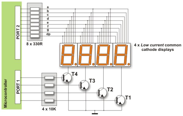
Here is an explanation on the figure above. First a byte representing units is applied on a microcontroller PORT2 and the transistor T1 is activated at the same time. After a while, the transistor T1 is turned off, a byte representing tens is applied on the PORT2 and the transistor T2 is activated. This process is being cyclically repeated at high speed for all digits and corresponding transistors.
A disappointing fact which indicates that the microcontroller is just a kind of miniature computer designed to understand only the language of zeros and ones is fully expressed when displaying any digit. Namely, the microcontroller does not know what units, tens or hundreds are, nor what ten digits we are used to look like. For this reason, each number to be displayed must go through the following procedure:
First of all, a multi digit number must be split into units, tens etc. in a special subroutine. Then each of these digits must be stored in specific bytes. Digits get recognizable appearance by performing ‘masking’. In other words, the binary format of each digit is replaced by a different combination of bits using a simple subroutine. For example, the digit 8 (0000 1000) is replaced by the binary number 0111 1111 in order to activate all LEDs displaying the digit 8. The only diode remaining inactive here is reserved for the decimal point.
If a microcontroller port is connected to the display in such a way that bit 0 activates segment ‘a’, bit 1 activates segment ‘b’, bit 2 segment ‘c’ etc., then the table below shows the mask for each digit.
In addition to digits from 0 to 9, there are some letters- A, C, E, J, F, U, H, L, b, c, d, o, r, t, that can also be displayed by masking.
In the event that common anode displays are used, all ones contained in the previous table should be replaced by zeros and vice versa. Additionally, PNP transistors should be used as drivers.
OPTOCOUPLER
An optocoupler is a device commonly used to galvanically separate microcontroller electronics from any potentially dangerous current or voltage in its surroundings. Optocouplers usually have one, two or four light sources (LED diodes) on their input while on their output, opposite to diodes, there is the same number of elements sensitive to light (phototransistors, photo-thyristors or photo-triacs). The point is that an optocoupler uses a short optical transmission path to transfer a signal between the elements of circuit, while keeping them electrically isolated. This isolation makes sense only if diodes and photosensitive elements are separately powered. In this way, the microcontroller and expensive additional electronics are completely protected from high voltage and noises which are the most common cause of destroying, damaging or unstable operation of electronic devices in practice. The most frequently used optocouplers are those with phototransistors on their outputs. When it comes to the optocouplers with internal base-to-pin 6 connection (there are also optocouplers without it), the base can be left unconnected.
For more detail: PIC Microcontrollers – Programming in C
- What basic connections are necessary for a microcontroller to operate?
Power supply, reset signal, and clock signal are necessary for proper operation. - Can the PIC16F887 operate at different supply voltages?
Yes, but a 5V DC supply with an LM7805 regulator is recommended for stability and reliability. - How is the reset implemented for safe microcontroller restart?
A push button tying MCLR to GND with a 10K pull-up resistor to VCC lets the microcontroller be reset safely. - What oscillator modes does the microcontroller support?
It supports LP (Low Power Crystal), XT (Crystal/Resonator), HS (High Speed Crystal/Resonator), and RC (Resistor/Capacitor) modes. - How can contact bounce from switches be prevented?
Use an RC debouncing circuit, an RS flip-flop hardware solution, or a software debounce that rechecks input after a delay. - How should LEDs and 7-segment displays be protected from damage?
Always use current limiting resistors for each LED segment and observe maximum current limits for microcontroller pins. - What is the purpose of multiplexing displays?
Multiplexing reduces the number of I/O pins needed by activating one digit at a time rapidly to create the illusion all digits are lit. - Why use a flyback diode with a relay coil?
An inverted polarized diode across the coil prevents high voltage spikes caused by sudden current stop through the coil. - When should an optocoupler be used with a microcontroller?
Use an optocoupler to galvanically isolate the microcontroller from potentially dangerous voltages or noisy environments.