


PIC 16F88 Digital Thermometer Light Meter and resistance ohm meter.
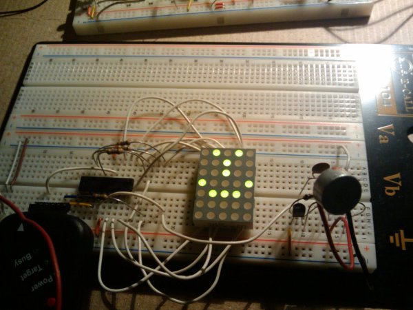
My original idea for this project was simply to try and interface the WINTEK WD-C2401P lcd panel to the pic (see my previous post). I figured it would be fun to add a couple of ADC readings to display something useful on the lcd.
Theory of Operation:
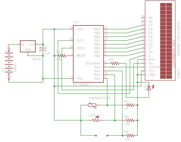
PORTB on the PIC is used as the data port for the LCD. The Enable, Register Select and Reset are tied to PORTA. Once the LCD is initialized, the PIC reads the ADC values from the thermistor, CDS cell and resistor (if connected) via a voltage divider. The voltage divider translates any change in resistance from the sensors into changes in voltage. The Vout is calculated as Vdd*(R2/R2+R1). ) So any change in R1 (the sensor's resistance) will result in a change in the output voltage. In order to translate this into the ADC value, a 10 bit ADC resolution microcontroller will have 1024 (2 to the power of 10) possible steps. So if the controller is operating on 5V then each step will increment the voltage by 5/1024 = 0.004882813V every increment. So the value in the ADC will be the voltage input at the ADC divided by 0.004882813. This allows for an accurate calculation of the resistance of the sensor. In order to translate the resistance to useful human readable form, its necessary to calibrate the sensors using real life instruments and extrapolating the values to the resistance offered. Since the display does not have any backlight, an LED is connected to PORTA4 to turn on whenever the light falls below a certain threshold.
Parts:
PIC 16F88
78L05 Voltage regulator
C1 - 1uf capacitor
R1,R3,R4 - 10K Ohm
R2 - 1K Ohm
R5 - 120 Ohm
LED
Thermistor
CDS Cell
Wintek WD-C2401P LCD display
For more detail: PIC 16F88 Digital Thermometer Light Meter and resistance ohm meter.
Related projects
Exploring the PIC16F88 Microcontroller for Remote-Controlled Robotics
I. Design Summary The objective of this mechatronics system design project is to develop a straightforward control and interface platform for robotics...
Meters & Test Instruments · PIC16F688Determine capacitance by measuring the charging time using PIC16F688
When TEST botton is pressed, RA3 pin is set to "1". R2 and R3 are divide the voltage to 1/2 Vra3 which...
Beginner Tutorials · PIC16F1827Breadboard module for 18-pin PIC16F microcontrollers (PCB version)
Because of their compact size, ease of use and many built-in peripherals, the 18-pin PIC16F series processors (PIC16F628A, PIC16F88, and now PIC16F1827/47)...
Meters & Test InstrumentsFrequency Meter Using Microcontroller
This tutorial simply states how to calculate frequency of a pulse source using a microcontroller. Story https://youtu.be/NAoj-HLRIro This tutorial simply states how...
Meters & Test Instruments · PIC16F84ADigital thermometer with PIC16F84 circuit
This electronic project is a very simple thermometer that is based on the PIC16F84A microcontroller, designed by Microchip. Why to use a...
Meters & Test InstrumentsProjects on Speed Checker To Detect Rash Driving On Highways
While driving on highways, drivers should not exceed the maximum speed limit permitted for their vehicle. However, accidents keep on occurring due...

Ibrar Ayyub
I am an experienced technical writer holding a Master's degree in computer science from BZU Multan, Pakistan University. With a background spanning various industries, particularly in home automation and engineering, I have honed my skills in crafting clear and concise content. Proficient in leveraging infographics and diagrams, I strive to simplify complex concepts for readers. My strength lies in thorough...