Summary of PCA9550 LED Driver With Programmable Blink Rates
This project demonstrates using the PCA9550 LED driver to control two LEDs with two fully programmable blink rates (0.172–44 Hz). Its internal oscillator needs no external components, supports I2C/SMBus, allows per-output ON/OFF/blink commands, and provides GPIO expansion. Each output sinks up to 25 mA (50 mA package), includes active LOW reset and POR, and supports one address pin for two-device bus operation. The device reduces bus traffic and offloads timing from the I2C master.
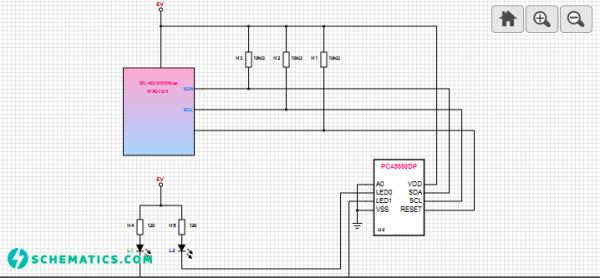
Parts used in the PCA9550 LED blinker project:
- PCA9550 LED driver IC
- Two LEDs
- Microcontroller or I2C/SMBus master (MCU, MPU, or DSP)
- Pull-up resistors for I2C bus (SDA and SCL)
- Current-limiting resistors for LEDs
- Power supply (VCC appropriate for PCA9550 and LEDs)
- RESET pin connection (active LOW hardware reset)
- Address pin wiring for device addressing
- Optional PCB or breadboard and wiring
This project introduces the use of PCA9550, an LED driver that causes the 2 LEDs to ON/OFF or in a flashing state at programmable rate. It has 2 selectable, fully programmable blink rates between 0.172Hz and 44Hz or 5.82 seconds and 0.023 second respectively. Its internal oscillator does not require external components and I2c bus interface logic is compatible with SMBus.
 The PCA9550 LED blinker drives LEDs in I2C-bus and SMBus applications where it is necessary to limit bus traffic or free up the I2C Master’s (MCU, MPU, DSP chip set, etc.) timer. The uniqueness of this device is the internal oscillator with two programmable blink rates. This LED blinker requires only the initial set-up command to program BLINK RATE 1 and BLINK RATE 2 (i.e., the frequency and duty cycle). From then on, only one command from the bus master is required to turn each individual open-drain output ON, OFF, or to cycle at BLINK RATE 1 or BLINK RATE 2. Maximum output sink current is 25 mA per bit and 50 mA per package. Any bits not used for controlling the LEDs can be used for General Purpose I/O (GPIO) expansion. The active LOW hardware reset pin (RESET) and Power-On Reset (POR) initializes the register to their default state, all zeroes, causing the bits to be set HIGH (LED OFF). One hardware address pin on the PCA9550 allows two devices to operate on the same bus.LED drivers can enable dimming and color changing or sequencing of LEDs initiated by preset commands, occupant presence, or manual commands.
For more detail: PCA9550 LED Driver With Programmable Blink Rates
- What blink rate ranges are programmable with the PCA9550?
Two selectable blink rates programmable between 0.172 Hz and 44 Hz (5.82 seconds to 0.023 second). - Does the PCA9550 require external components for its oscillator?
No, its internal oscillator does not require external components. - How are LED states controlled after initial setup?
After programming the two blink rates, one command from the bus master can turn each output ON, OFF, or set it to blink at BLINK RATE 1 or BLINK RATE 2. - What is the maximum output sink current per bit and per package?
Maximum output sink current is 25 mA per bit and 50 mA per package. - Can unused LED outputs be used for other purposes?
Yes, any bits not used for LEDs can be used for General Purpose I/O expansion. - How does the device initialize its registers on reset or power-up?
The active LOW RESET pin and Power-On Reset initialize registers to default zeroes, causing bits to be set HIGH (LED OFF). - Is the PCA9550 compatible with SMBus?
Yes, the I2C bus interface logic is compatible with SMBus. - How many PCA9550 devices can share the same I2C bus using the address pin?
One hardware address pin allows two devices to operate on the same bus. - Why use the PCA9550 in I2C-bus applications?
It limits bus traffic and frees the I2C master from timing duties by providing internal programmable blink control.