Summary of RT1720 Hot Swap Controller Protection Circuit for Overvoltage and Overcurrent
This article presents a protection circuit using the Richtek RT1720 IC to guard against overvoltage, overcurrent, transients, and reverse polarity. It explains features, circuit operation, component selection, calculations for fault timer, current-sense resistor, and overvoltage threshold, PCB construction tips, test setup and results, and typical applications like automotive surge protection and hot-swap systems.
Parts used in the RT1720 Protection Circuit:
- RT1720 IC
- MMBT3904 transistor
- 1000pF capacitor
- 1N4148 (BAT20J) diode
- 470µF, 25V capacitor
- 1µF, 16V capacitor
- 100k, 1% resistors (4)
- 25mΩ resistor (current sense)
- IRF540 MOSFETs (2)
- 30V DC power supply
- 5mm connectors (2)
- Cladboard (handmade PCB)
Oftentimes in an electronic circuit, it’s absolutely necessary to use a special protection unit to protect the circuit from overvoltage, overcurrent, transient voltage, and reverse polarity and so on. So, to protect the circuit from these surges, Richtek Semiconductor introduced the RT1720A IC which is an oversimplified protection IC designed to meet the needs. The low-cost small size and very few component requirements make this circuit ideal to be used for many different practical and embedded applications.
So, in this article, I am going to design, calculate, and test this protection circuit and at last, there will be a detailed video showing the working of the circuit, so let’s get started. Also, check our previous protection circuits.
IC RT1720
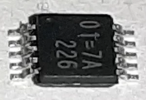
It’s a low-cost protection IC designed to simplify implementation. A fun fact about the IC is that the size of this IC is just only 4.8 x 2.9 x 0.75 mm. So, do not get fooled by the image, this IC is extremely tiny, and the pin pitch is just only 0.5mm.
IC RT1720 Features:
- Wide Input Operation Range: 5V to 80V
- Negative Input Voltage Rating to −60V
- Adjustable Output Clamp Voltage
- Adjustable Over-Current Protection
- Programmable Timer for Fault Protection
- Low Shutdown Current
- Internal Charge Pump N-MOSFET Drive
- Fast 80mA MOSFET Shut-off for Overvoltage
- Fault Output Indication
The features list and the dimension parameters are taken from the datasheet.
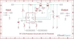
Circuit Diagram
As mentioned earlier this circuit can be used for:
- Transient voltage surge suppressor
- Overvoltage protection circuit
- Overcurrent protection circuit
- Surge protection circuit
- Reverse polarity protection circuit
Also, check our previous protections circuits:
- Inrush Current Limiting using NTC Thermistor
- Overvoltage Protection Circuit
- Short-Circuit Protection Circuit
- Reverse Polarity Protection Circuit
- Electronic Circuit Breaker
Components Required
| Sl.No | Parts | Type | Quantity |
| 1 | RT1720 | IC | 1 |
| 2 | MMBT3904 | Transistor | 1 |
| 3 | 1000pF | Capacitor | 1 |
| 4 | 1N4148(BAT20J) | Diode | 1 |
| 5 | 470uF,25V | Capacitor | 1 |
| 6 | 1uF,16V | Capacitor | 1 |
| 7 | 100K,1% | Resistor | 4 |
| 8 | 25mR | Resistor | 1 |
| 9 | IRF540 | Mosfet | 2 |
| 10 | Power Supply Unit | 30V, DC | 1 |
| 11 | Connector 5mm | Generic | 2 |
| 10 | Cladboard | Generic | 1 |
How this Protection Circuit Works?
If you look closely at the above schematic, you can see there are two terminals one’s for input and other for output. The input voltage is fed through the input terminal.
The 100K pull-up resistor R8 pulls the SHDN pin high. So, by making this pin high enables the IC.
The 25mR resistor R7 sets the current limit of this IC. If you want to know how I got the 25mR value for the current sense resistor, you can find it in the calculation section of this article.
The Transistor T1, diode D2, resistor R6, and the MOSFET Q2 all together form the reverse polarity protection circuit. In general, when voltage is applied to the VIN pin of the circuit the voltage first pulls the SHDN pin High and powers the IC via VCC pin then it flows through the current sense resistor R6 now the diode D2 is in forward-bias condition, this makes the transistor T1 on and current flows through the transistor which makes the MOSFET Q2 on which also makes the Q1 on and now current can flow right through the MOSFET onto the load.
Now when a reverse voltage is applied to the VIN terminal the diode D2 is in reverse bias condition and now cannot flow through the MOSFET. The resistor R3 and R4 form a voltage divider which acts as feedback that enables overvoltage protection. If you want to know how I calculated the resistor values, you can find it in the calculation section of this article.
MOSFET Q1 and Q2 form an external N-MOSFET load switch. If the voltage rises above the set voltage which is set by the external feedback resistor exceeds the threshold voltage the RT1720 IC line regulates using the external load switch MOSFETs, until the adjustable fault timer trips and turns the MOSFET off to prevent overheating.
When the load draws more than the current set-point (set by the external sense resistor connected between SNS and VCC) the IC controls the load switch MOSFET as a current source to limit the output current, until the fault timer trips and turns off the MOSFET. Also, the FLT output goes low, signaling a fault. The load switch MOSFET remains on until VTMR reaches 1.4V, giving time for any system housekeeping to occur before the MOSFET turns off.
The RT1720 open-drain PGOOD output rises when the load switch turns on fully and the MOSFET’s source approaches its drain voltage. This output signal can be used to enable downstream devices or to signal a system that now normal operation can begin.
The IC’s SHDN input disables all functions and reduces the VCC quiescent current down to 7μA.
Note: Details about the internal functionality and schematic is taken from the datasheet.
Note: This IC can withstand reverse supply voltages up to 60V below ground without damage
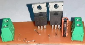
Circuit Construction
For demonstration, this overvoltage and over current protection circuit is constructed on a Handmade PCB with the help of the schematic; Most of the components used in this tutorial are surface mounted components hence, a PCB is mandatory for soldering and placing it all together.
Note! All the components were placed as closely as possible to reduce parasitic capacitance, inductance, and resistance
Calculations
The datasheet of this IC gives us all the details needed to calculate the Fault Timer, the overvoltage protection, and the overcurrent protection for this IC.
Fault Timer Capacitor Calculation
In the event of a long fault, GATE will turn on and off repeatedly. The on and off timings (tGATE_ON and tGATE_OFF) are controlled by the TMR charge and discharge currents (iTMR_UP and iTMR_DOWN) and the voltage difference between the TMR latch and unlatch thresholds (VTMR_L – VTMR_UL):
tGATE_ON = CTMR * (VTMR_L – VTMR_UL) / (iTMR_UP)
tGATE_ON = 4.7uF x (1.40V - 0.5V) / 25uA  = 169 mS
tGATE_OFF = CTMR * (VTMR_L – VTMR_UL) / (iTMR_DOWN)
tGATE_OFF = 4.7uF x (1.40V - 0.5V) / 3uA  = 1.41 S
Current Sense Resistor Calculation
The current sense resistor can be calculated by the following formula
Rsns = VSNS/ILIM
          = 50mV / 2A = 25mR
Note: The 50mV value given by the datasheet
Over-Voltage Protection Calculation
VOUT_OVP = 1.25V x (1+ R2/R1)
                     = 1.25 x (1+ 100k/10k)
                     = 1.25 x (11)
                     = 13.75V
Testing Over Voltage and Current Protection Circuit
To test the circuit, the following tools and setup is used,
- 12V Switch Mode Power Supply(SMPS)
- Meco 108B+ Multimeter
- Hantech 600BE USB PC Oscilloscope
To construct the circuit, 1% Metal Film Resistors are used and the tolerance of the capacitors is not taken into account.
The room temperature was 22 degrees Celsius during testing.
The Test Setup
The following setup is used to test the circuit
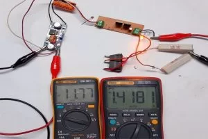
For demonstration purpose, I used a buck converter to vary the input voltage of the circuit
- The 10 Ohms power resistors are acting as loads,
- The switch is there to quickly add excess load. You can observe it in the video given below.
- The mecho 108B+ showing the input voltage.
- The mecho 450B+ showing the Load Current.
Now as you can see in the above image I have increased the input voltage and the IC starts to limit the current because it is in fault condition now.
If the working principle of the circuit is not clear to you please watch the video.
Note: Please note that for demonstration purposes I have increased the value for the fault timer.
Applications
This is a very useful IC and can be used for many applications, some of them listed below
- Automotive/Avionic Surge Protection
- Hot-Swap/Live Insertion
- High-Side Switch for Battery-Powered Systems
- Intrinsic Safety Applications
- Reverse Polarity Protection
I hope you liked this article and learned something new. Keep reading, keep learning, keep building and I will see you in the next project.
- What protection functions does the RT1720 circuit provide?
It provides overvoltage, overcurrent, transient voltage suppression, and reverse polarity protection. - What input voltage range does the RT1720 support?
The RT1720 supports a wide input range from 5V to 80V. - How is the current limit set in this circuit?
The current limit is set by the external sense resistor; the article uses a 25mΩ sense resistor calculated from VSNS = 50mV and ILIM = 2A. - How is the overvoltage threshold calculated?
VOUT_OVP is calculated as 1.25V x (1 + R2/R1); with R2 = 100k and R1 = 10k the threshold is 13.75V. - What components form the reverse polarity protection?
Transistor T1, diode D2, resistor R6, and MOSFET Q2 form the reverse polarity protection. - What does the FLT output indicate?
The FLT output goes low to signal a fault when the load current exceeds the set point and the fault timer trips to turn off the MOSFET. - How long are the gate on and off times for the chosen CTMR?
With CTMR = 4.7µF, tGATE_ON ≈ 169 ms and tGATE_OFF ≈ 1.41 s as calculated in the article. - What is the function of the PGOOD output?
The PGOOD open-drain output rises when the load switch turns on fully and the MOSFET source approaches its drain voltage, indicating normal operation. - What is the shutdown (SHDN) behavior of the IC?
Driving SHDN low disables all functions and reduces the VCC quiescent current to about 7µA. - What applications are suggested for this protection circuit?
Suggested applications include automotive/avionic surge protection, hot-swap/live insertion, high-side switching for battery systems, intrinsic safety, and reverse polarity protection.