Summary of OSOMCOM POCSAG BTS using pic microcontoller
The article describes a low-cost Base Transmitter Station (BTS) for POCSAG pagers, featuring a PIC 18F14K22 microcontroller and an ADF7012 UHF transmitter. Designed for under $15, the board supports various modulations and frequencies from 75MHz to 1GHz. It communicates via UART/RS232 and includes firmware for sending messages, configuring parameters, and performing mass sends or tests. The project is versatile, suitable for generic radio transmission experiments beyond just paging.
Parts used in the POCSAG BTS:
- PIC 18F14K22 Microcontroller
- ADF7012 UHF Transmitter Module
- MCP1700T-3302 Low-Drop Voltage Regulator
- 4MHz Crystal Oscillator (Q1)
- L1 Coil (8.7 nH)
- SMA Connector for Antenna
- SV1 RS232 Connector
- SV2 General Purpose I/O Port
- SV3 ICD Debug Port
- Push-button Switch (S1)
The BTS or Base Transmitter Station is the device that transmit the POCSAG messages to the pager. It is the radio interface of the POCSAG network.
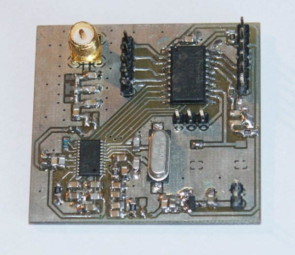
THE HARDWARE
The current version of the BTS hardware is a small board with a pic 18F microcontroller with a firmware that receive commands through an UART/RS232 port, create the POCSAG message and transmit it using the ADF7012 UHF transmitter.
This board has not be designed to be used exclusively with OSOMCOM POCSAG but to be used as a generic low power radio transmitter. Other uses of this board include experimenting with 433MHz keyboards, car/garage remotes, data links, APRS, etc.
The board has been designed to be very cheap (less than 15$) and easy to develop with.
 Board features
- CPU: PIC 18F14K22 @ 16MHz
- Memory: 16KB Flash / 512 Bytes RAM / 256 EEPROM
- Transmission frequency: selectable from 75MHz to 1GHZ (but some parts values may need to be changed. More about this later)
- Supported modulations: FSK/GFSK/OOK/GOOK/ASK. (FSK is used for POCSAG)
- Transmission bitrate: selectable up to 179.2 kbps (512/1200/2400 for POCSAG)
- Transmission power: selectable up to 14 dBm (20mW)
- UART/RS232 port
- Debugging/programming port for ICD/PICKIT
- Expansion port with 4 GPIOs
- SMA connector for antenna
- Power: 3.3 volts ; ~50mA
- Size: 4.4 cm x 4.6 cm
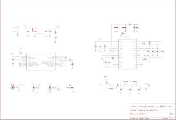
Power supply
The power supply has a very simple and standard design.
The 5 volts input is transformed to a 3.3 volts supply using the MCP1700T-3302 low-drop voltage regulator from Microchip. C1, C2 and C3 filter the input and output power.
A diode protecting the input from a reversed connection could be handy, but I didnt put it in the design. I am just confident that the user is not that stupid…
– Microcontroller
The brain of the board is a Microchip PIC 18F14K22.
– The radio module
A ADF7012 from Analog Devices is used as radio module.
This handy UHF low-power radio transmissor supports FSK, GFSK, OOK, GOOK and ASK modulation at a maximum rate of 179.2 kbps and the integrated Power Amplifier can deliver up to 20 mW without using an external antenna driver.
An internal PLL with selectable divisor synthesize almost any desired output frequency in a range from 75MHz to 1GHZ using just a 4MHz quartz.
A SPI interface is used to configure the transmisor. Modulation scheme, output power, output frequency and other transmission parameters are selectable through this interface.
In my opinion, due its versatility, flexibility and simplicity to use, this is one of the best sub-GHz integrated transmisor out there. However, the lack of documentation and examples make it a little bit frustrating to work when you are starting. The datasheet is sometime confusing and sometimes insufficient. For example, it doesn’t give a table or graph with the output impedance of the RF output. HOW THE HELL ARE YOU GOING TO MATCH THE ANTENNA IF YOU DONT KNOW THE IMPEDANCE? Of course… you can always use a network analyzer and measure it, but unfortunately I don’t have access to one, so I just did my best trying to guess the impedance at my working frequency using the schematics of the application examples. They are for different frequencies, but I did an interpolation and… it works more or less fine.
I don’t want to make a deep explanation of the design process and inner working of the radio module, but I will make a brief description of the function of the different parts. If you need more information, refer to the ADF7012 datasheet.
The Q1 4MHz crystal define the output frequency.
To be more exact, the crystal frequency defines the output frequency resolution. The output frequency is a defined with the equation
Fout = Fcrystal · (N/R) · OD
being N a 8+12 bits fractional number, R a 4 bits integer number and OD (Output Divider) is 1,2,4 or 8. The value of N,R and OD are selectable through the SPI interface.
In theory, almost any output frequency is selectable with almost any input frequency, but choosing a lower frequency crystal gives you more resolution and introduces less spurious noise.
In case we use FSK or GFSK, the crystal frequency also defines the frequency deviation resolution:
Fdeviation = (Fcrystal / R) · (M / 4096)
M (Modulation Number) is a software selectable 9 bits integer number.
The L1 coil controls the VCO frequency. The value of the coil has to be chosen according to the desired output frequency. The current value of 8.7 nH is appropiate to work in the frequency ranges of 70-77.5 MHz, 140-155MHz , 280-310 MHz and 560-620MHz. If you would like to personalize the circuit to make it work in a different frequency, you have to refer to the datasheet graph and choose an appropiate inductance value.
The Loop Filter formed with C10, C11, C12, C13, C14, C15, R4, R5 and R6 filters the VCO tunning voltage. In practice, the bandwith of this filter limits the maximum transmision datarate. When using FSK, the bandwith of this filter should be three times the bandwith of the data rate.
The easiest way to calculate the values of the filter is using the “ADI SRD Design Studio” software availabe for free in the Analog Device website.
For our current needs, a 30KHz filter bandwith has been implemented.
The antenna matching network
As commented before, the RF output impedance of the ADF7012 at 150MHz is an unknow, so the antenna matching is not easy without the proper resources.
I don’t have a network analyzer to measure the output impedance so I did some guess and some try-and-error process. The result is not perfectly matches but is good enough as the transmisor signal range is more or less the expected for a 20 mW emission.
Be aware that L4, L6 and L8 are unpopulated. I put those coil footprints in the PCB just in case a fine tuning is required by adding another coil or capacitor in parallel.
If you need to modify the BTS schematic to transmit in a different frequency than 140-160MHz, you have to change this antenna matching network to adapt it to your needs.
If you want to work with 315, 433, 868 or 915 MHz, you can use the matching network recommend in the datasheet.
– I/Os and connectors
S1 is a push-button that can be used to launch in the firmware some tasks.
SV1 is a RS232 connector to communicate with the BSC or a host computer. It uses 3.3v signals but is tolerant to 5v. You can use a RS232 TTL – USB bridge to connect the BTS to your computer BSC system.
SV2 is a General Purpouse I/O port. It has 4 free GPIOs that can be connected to any sensor or system. GP1 is also an analog input, so an analog sensor like a temperature sensor can be connected.
SV3 is the ICD debug port. The microcontroller can be programmed or debugged with an ICD, PICKIT or similar device.
THE FIRMWARE
The last version of the firmware can be downloaded here.
The firmware has been written in C using the MPLAB X IDE and the XC8 compiler in free mode. It is important to compile it using the version 1.20 or superior of the XC8. Earlier versions dont optimize the code and the binary will not fit into the microcontroller.
The main function of the firmware is to transmit POCSAG encoded messages. However, in the firmware source there is a complete library to configure and control the ADF7012 radio module, so it would be easy to modify the firmware to transmit using other digital protocols.
USAGE AND COMMANDS
The best way to use the POCSAG BTS is connecting it to a device or computer running the Osomcom POCSAG BSC software and let the BSC to control the BTS. However, if you need something simple you can just connect the BTS to your computer’s RS232 port using a USB-RS232 converter and use a terminal program to send commands to the BTS. The current firmware puts in the RS232 port a command console that can be used to configure the BTS and send messages.
The configuration of the RS232 is 9600 Bauds 8-N-1.
The current available commands are:
– SEND (A|N|I) RIC MESSAGE:
Send a POCSAG message to the specified RIC. The first parameter indicates if the message has to be send like an Alphanumeric message, a Numeric message or an Idle message.
An hexadecimal representation of the sent batches is printed.
– CONFIG [PARAM] [VALUE]:
The config command without arguments prints a list of the configurable parameters and their current value. To set a new value, send the parameter name and the new value with the CONFIG command.
This is the list of the available parameters:
- FREQ: Frequency in Herzs. If you set a frequency that is not reacheable by the BTS hardware, it will complaint with a ‘Init error’ message when it start to transmit (SEND, START_MS or TEST command).
- DEVIATION: FSK deviation in Herzs. In POCSAG, the most common value is 4500.
- BAUDS: 512, 1200 or 2400.
- POWER: The RF output power. The value is in the range between 0 (-20dBm) and 32 (13dBm).
- MS_SAVE_FREQ: Number of RICs between status saving when doing a ‘Mass Send’ (more info below)
- MS_DELAY: wait time in milliseconds between the transmision of two batches of 8 messages when doing a ‘Mass Send’.
– SAVECFG:
Saves the current config in the EEPROM. The configuration is restored when the board is powered.
– LOADCFG:
Restores the config stored in the EEPROM.
– START_MS START_RIC STOP_RIC:
Start a ‘Mass Send’. It sends a message with a single ‘A’ character to all the RICs between the START_RIC and STOP_RIC. It is useful to scan RICs, when you don’t know the RIC of your pager.
8 messages for 8 consecutives RICs are packed and transmited in a single POCSAG Batch. Between two batches, some time defined by the MS_DELAY config parameter is waited.
Every MS_SAVE_FREQ number of RICs scanned, the current status of the Mass Send is stored in the EEPROM. In case the power supply is disrupted, the firmware will automatically continue with the Mass Send from the last saved status.
STOP_MS:
Stops the Mass Sending.
– RESUME_MS:
Continue with the stopped Mass Sending.
– STATUS_MS:
Shows the current state of the Mass Send (current RIC and stop RIC)
– TEST [0|1|2]:
Transmits a continous test signal with the selected pattern: ’000000…’ (TEST 0), ’111111…’ (TEST 1) or ’101010…’ (TEST 2).
I use this function to know if the ADF7012 is transmiting at the desired frequency and deviation.
– STOP_TEST:
Stops the transmition of the TEST signal.
TROUBLESHOOTING
If you have problems making the BTS to work, check the next things:
– Is every thing correctly connected/soldered? Double check the soldered parts. Are them the correct parts?
– Is the microcontroller programed?
– Is the board being powered with a 5 volts power supply? Anything between 3.7 and 6 volts should be OK.
You can know if the board is being correctly powered because one led will be light.
– Connect the BTS board to your computer using a USB-RS232 board. Open a terminal program and set it to 9600 bauds, 8-N-1. Power the board and you will see a welcome message (‘Osomcom POCSAG 0.3′). If you send any string, the board will respond with a help menu.
If you can’t make work the RS232 shell, you probably have a problem with the microcontroller. If you can get the shell but you can’t transmit anything, the problem is probably in the radio module.
– Check if there is any transmission. The best and cheapest way to do this is using an RTL-SDR dongle. I use it like an spectrum analyzer.
Open the command shell, configure the desired frequency and deviation and use the TEST 2 command to generate a test pattern signal.
If it says ‘Init Error’, the BTS can’t reach the configured frequency. Choose another frequency or if you are interested in transmitting in that one, modify the schematics (the VCO coil and the antenna matching) as suggested in the Hardware section.
For more detail: OSOMCOM POCSAG BTS
- What is the primary function of the BTS hardware?
The device transmits POCSAG messages to pagers and serves as the radio interface for the POCSAG network. - Can this board be used for purposes other than OSOMCOM POCSAG?
Yes, it is designed as a generic low-power radio transmitter for experimenting with 433MHz keyboards, car remotes, data links, and APRS. - How do you configure the transmission frequency on the board?
You set the frequency using the CONFIG FREQ command followed by the value in Hertz. - What is the recommended baud rate for the RS232 connection?
The configuration requires 9600 Bauds, 8 data bits, no parity, and 1 stop bit (8-N-1). - How can you verify if the radio module is transmitting correctly?
Use the TEST 2 command to generate a signal pattern and check for transmission using an RTL-SDR dongle. - What happens if the power supply is disrupted during a Mass Send?
The firmware automatically resumes the Mass Send from the last saved status stored in the EEPROM. - Which compiler version is required to build the firmware?
You must use XC8 compiler version 1.20 or superior to ensure the binary fits into the microcontroller. - What voltage range is acceptable for powering the board?
The board accepts any input between 3.7 and 6 volts, which is regulated down to 3.3 volts.