Summary of Oscilloscope clock
This article details building an oscilloscope clock using a Microchip PIC microcontroller driven by a 32.768 Hz watch crystal. The system displays time in HH:MM:SS format by generating specific voltage waveforms scanned across the oscilloscope's horizontal axis. The design involves creating a custom 7x5 dot-matrix character set, digitizing these characters into binary data for the microcontroller, and assembling the software. The hardware circuit is minimal, utilizing a weighted resistor DAC to convert digital signals to analog voltages for display on an oscilloscope or computer sound card input.
Parts used in the Oscilloscope Clock:
- Microchip PIC12F510, PIC12F509, or PIC12F508 microcontroller
- 32768 Hz watch crystal
- Electrolytic capacitor
- Two 15 pf capacitors (optional)
- 10K resistor
- 47 K resistor
- 22 K resistor
- 12 K resistor
- 1 Megohm series resistor
- Copper clad board
- Line in jack of a sound card
- Shielded cable
Step 1: Design the character set
On an oscilloscope screen, vertical axis (up and down) corresponds to the magnitude of the voltage and horizontal axis (across) corresponds to time.
Letters and numbers are made visible by assigning a voltage to each dot, vertically, and using time to scan across it. If a dot is to be made visible, a particular voltage is output during its time slot. If the dot is invisible, a blanking voltage is output during that time instead. 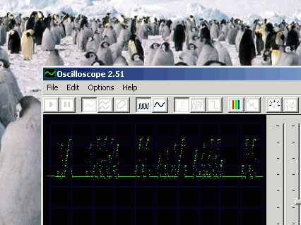
Since we are using a programmable microcontroller, the characters to be displayed will be held as dot patterns in its program memory. We thus have the freedom to design the character set for the clock. I have used a 7×5 matrix font, and used graph paper to design the characters.
It is simple. Just grab a pen and mark inside the squares of the 7×5 area, and try to make the result look like letters and numbers.
Get lots of paper, so that you can throw away your mistakes and start all over again.
Or, you can download the data sheet of some LCD controller ic and it will have all those character maps listed inside. Copy away, and no one will ever suspect that this work is not your own.
Step 2: Digitise each character
Now you have to convert each character into numbers to be incorporated into the microcontroller program. Each byte holds eight bits, so five bytes will hold one 7×5 matrix character as ones and zeroes.
A blank square is zero. A filled square is a one. One bit in each byte will remain unused.
The microchip assembler directive “dt” will cause the value following it to be converted into a “retlw” intruction.
The number in the form ” b’nnnnnnn’ ” will be interpreted as a binary number.
In this case, I have decided to make the top of the character be represented by the most significant bit of the byte.
This process will have to be repeated for each character that you wish to display.
Step 3: The program
I have made it in two parts: the character generator part is in a separate include file, “chargen.inc”, and the main program is the file “clock510.asm”. When you assemble it with MPLAB, you get the file “clock510.hex” which has to be programmed into a Microchip PIC12F510, PIC12F509 or PIC12F508. The same hex file will work for all three processors. The circuit is shown in ASCII form in the program itself.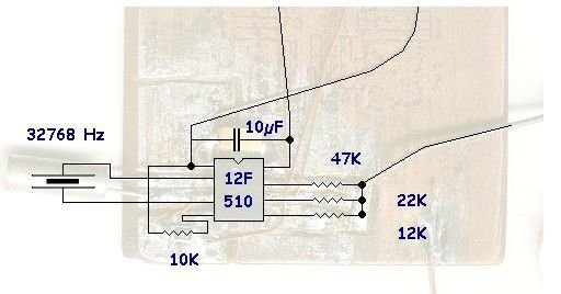
Step 4: The circuit
The circuit is very simple. The eight pin microcontroller was mounted on a piece of scrap copper clad board after cutting out eight islands for the eight leads. An electrolytic capacitor was connected across the supply leads. A crystal taken from an old watch was fitted across leads 2 & 3. Two 15 pf capacitors are also to be fitted, but mine seems to work without it. Your Mileage May Vary. The MCLR/Vpp lead was pulled up to Vdd with a 10K resistor.
The remaining three leads connect to three resistors forming a crude weighted resistor DAC.
GPIO0 has a 47 K resistor.
GPIO1 has a 22 K resistor. This should be half the previous value, about 23.5 K, but this value is close enough.
GPIO2 has a 12 K resistor, close to the ideal value of 11K.
The other ends of the resistors are connected together, and I used a series resistor of 1 Megohm and connected it to the Line in jack of the sound card in my computer using shielded cable.
The thin wires in the picture are actually enamelled copper, and so will not short to one another if they touch. They go to
For more detail: Oscilloscope clock
- How does the microcontroller generate visible characters?
It assigns a specific voltage to each dot vertically and uses time to scan across horizontally, outputting a blanking voltage for invisible dots. - What font matrix size was used for the character set?
A 7x5 matrix font was designed using graph paper where filled squares represent ones and blank squares represent zeros. - Which microcontrollers are compatible with the provided hex file?
The same hex file works for the Microchip PIC12F510, PIC12F509, or PIC12F508 processors. - Can the project work without the 15 pf capacitors?
Yes, the author notes that the circuit seems to work without them, though their mileage may vary. - How is the analog signal sent to the computer?
The weighted resistor DAC connects via a 1 Megohm series resistor and shielded cable to the Line in jack of a sound card. - What is the function of the MCLR/Vpp lead in this circuit?
The MCLR/Vpp lead is pulled up to Vdd using a 10K resistor. - How many bytes are required to store one 7x5 character?
Five bytes are needed to hold one 7x5 matrix character as ones and zeroes, leaving one bit unused per byte. - What tool is used to assemble the program files?
MPLAB is used to assemble the source files into a .hex file for programming the microcontroller. - What type of wire is recommended for connecting the resistors?
Enamelled copper wire is used because it will not short to one another if they touch. - Does the top of the character correspond to the most significant bit?
Yes, the design makes the top of the character be represented by the most significant bit of the byte.