Summary of make your own wearable LED display using pic-microcontroller
This article details the construction of a wearable LED display on fabric, covering design, matrix architecture for efficient control, and sewing techniques. It lists necessary supplies like conductive thread, surface-mount LEDs, microcontrollers, and tools, while offering troubleshooting tips and programming advice, recommending the LilyPad Arduino for ease of use over traditional AVR chips.
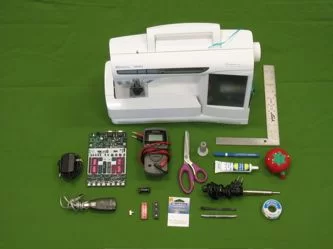
Parts used in the Wearable LED Display:
- Conductive thread
- Surface mount LEDs
- Microcontroller with internal oscillator (e.g., AVRmega16 or LilyPad Arduino)
- IC socket for the microcontroller
- Battery and holder (or LilyPad power supply)
- On/off switch
- 30 watt soldering iron and lead-free solder
- Multimeter
- T-square or ruler
- Silver and brass crimping beads
- Garment or fabric with pattern
- Needles, fabric marker, and fabric glue
- Scissors
- Sewing machine
jump to a section:supplies
about LED arrays
design
construction
customizing/programming
washing and wearing
troubleshooting and FAQ
**NOTE** As of Fall 2007, skip the ugly microcontroller programming (don’t buy the STK500 or the AVR chip)… Get a LilyPad Arduino instead. It’s much easier to sew and to program! See my LilyPad Arduino tutorial for help on getting started with the LilyPad.
- conductive thread
(You can purchase conductive thread from SparkFun. Check out my materials link page for more information on conductive threads.) - surface mount LEDs, as many as you want to include in your display
(I used a super intensity red LED from digikey. part #: 67-1695-1-ND ) - a microcontroller of your choice.
(Chose one with an internal oscillator. I used the AVRmega16. digikey part #: ATMEGA16L-8PC-ND) - an IC socket for your microcontroller.
(You want be able to sew through the socket’s holes after minimal modifications. For a 40 pin micorcontroller, digikey part #: A9440-ND will work after you drill out the holes. I found the perfect socket, one that required no drilling, browsing my local electroics store, so try that first.) - a battery and holder. ***As of Fall 2007, get a LilyPad power supply instead. Much easier!
(I used a standard 6 volt camera battery. part#: A544.
You can purchase the holder for this battery from digikey part #: 108KK-ND) - an on/off switch ***Not necessary if you use a LilyPad power supply
(Check out these slide switches and toggle switches from digikey.) - a 30 watt soldering iron and lead-free solder
(You’re going to wear this so keep health hazards like lead in mind!) - a multimeter
- a T-square or a ruler
- an assortment of silver and brass crimping beads, at least twice as many as you have LEDs
(These are available from your local bead shop, or from Michaels) - a garment or a piece of fabric and a pattern you can use to make your own garment.
- a needle or two, a fabric marker, and a bottle of fabric glue
(Needles, fabric markers, and Liquid Stitch, Sew-No-More, and similar products are available at your local fabric shop or Joann Stores) - a pair of scissors
- a sewing machine
about LED arrays
The naive way to power an array of LEDs would be to allocate one I/O pin of a microcontroller for each LED, tying the anode lead (+) of each LED to the microcontroller, and the cathode lead (-) to ground. This arrangement would quickly become unwieldy, requiring a chip with 100 pins to run a 10 x 10 matrix. Thankfully, we can exploit the essential property of diodes to implement a much more efficient design which will only require 20 pins to run a 10 x 10 array.
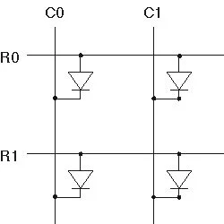
Diodes allow current to flow in only one direction. LEDs emit light when current flows through them. By exploiting this property, we can use the design shown below to power N LEDs with square root (N) microcontroller pins. As can be seen from the schematic, the LEDs are arranged in an row-column array with the anode end of each LED attached to a row and the cathode end of each LED attached to a column. Each row and each column is then attached to a microcontroller pin. The microcontroller can then be used to control each LED individually. For example, suppose we want only the LED at row0 column0 (LED R0 C0) turned on. To accomplish this, we first turn all of the LEDs off by setting all of the rows to ground and all of the columns to +5 volts, applying a reverse voltage to all of the LEDs. Then, to turn on LED R0 C0, we set R0 to +5V and C0 to ground. LED R0 C0 is the only LED with current running through it so it will emit light.
The matrix architecture allows us to control each LED individually, but does not give us complete flexibility. For example, it is impossible to simultaneously turn on only LED R0 C0 and LED R1 C1. To display complex patterns and animations, we exploit the shortcomings of human vision. To make it appear as though LED R0 C0 and LED R1 C1 are on at the same time, we quickly flash first LED R0 C0 and then LED R1 C1 and repeat this cycle for as long as we want the illusion to appear. As long as our eye can’t detect the flicker, we perceive only the diagonal line of light.
For more information on LEDs check out:
How LEDs work from Howstuffworks
LEDs from Wikipedia
Now, on with the project…
design
1. Pick a garment to sew on, a pattern that will let you sew your own garment, or design your own pattern.
2. Design your display. decide on the number of LEDs you want and their general placement. This will depend on the garment you chose and the microcontroller you intend to use as well as how you’d like the display to look. I decided to sew a simple tank top and I chose to place the LEDs evenly across my tank top every 2″. Since my tank top is approximately 28″ around and 12″ tall I needed 84 LEDs. (Note! The pictures here show a different shirt with 140 LEDs spaced 1″ apart.)
3. Decide on the microcontroller you want to use. Choose one with an internal oscillator, and make sure you have enough i/o pins to control your matrix. It’s a good idea to pick a microcontroller you are familiar with and read the data sheet carefully! It can take some reading to discover that what you thought was a general purpose I/O pin is input only or an open drain output.
4. Decide on the power-source you want to use.
construction
0. If you’re sewing your own garment, cut out the pieces and partially or fully assemble them.
1. Package your LEDs into sequins. Get out the crimping beads and surface mount LEDs. Tip an LED on its side. Using a soldering iron with a very clean tip, place the tip of the iron into a bead. Tin the bead with lead-free solder; melt some solder onto the outside of the bead. With the soldering iron, drag the bead up to the LED as is shown in the photo below. When the melted solder touches the LED’s contact, the bead will adhere to the LED. Lift the soldering iron out of the bead. If your soldering iron tip is dirty, it will stick to the bead and make the job very difficult. If this is happening you should clean or replace your tip. Once you get the hang of it, this should go pretty fast. You should be able to solder 100 LEDs within an hour.
You may want to take some measures at this stage to distinguish the cathode from the anode lead of each LED. The cathode end is often marked with a green line on the front or back of the surface mount package. To distinguish the two, you can solder a brass crimping bead to the cathode lead and a silver bead to the anode lead for each LED.
For more detail: make your own wearable LED display
- What is the recommended alternative to the STK500 and AVR chip as of Fall 2007?
The LilyPad Arduino is recommended because it is much easier to sew and program. - How does the matrix architecture reduce the number of required pins?
It uses square root of N pins to control N LEDs by arranging them in rows and columns rather than dedicating one pin per LED. - Can you turn on two diagonal LEDs simultaneously in this design?
No, it is impossible to simultaneously turn on only LED R0 C0 and LED R1 C1 due to the matrix limitations. - How can you create the illusion of multiple LEDs being on at once?
You quickly flash the LEDs in a cycle so fast that human vision perceives them as being on simultaneously. - What type of solder should be used for this project?
Lead-free solder must be used since the garment will be worn. - How can you distinguish the cathode from the anode lead of each LED?
You can solder a brass crimping bead to the cathode lead and a silver bead to the anode lead. - What is the best way to attach the crimping beads to the LEDs?
Use a clean soldering iron tip to tin the bead, then drag it up to the LED contact until the melted solder adheres the bead. - Does the battery holder need an on/off switch if using a LilyPad power supply?
An on/off switch is not necessary if you use a LilyPad power supply.