Summary of NJM2035 – HI-FI Stereo Encoder / Multiplexer using pic microcontoller
This article describes a compact HI-FI stereo encoder/multiplexer based on the NJM2035 IC and a 38 kHz crystal, producing clear stereo audio with good channel separation and stable pilot tone without calibration. It explains the three stages (pre-emphasis, digital encoder, mixer), technical specs, connection steps to an FM transmitter, and parts used for building the encoder.
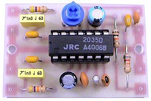
Parts used in the HI-FI Stereo Encoder / Multiplexer:
- 2x 47K resistors
- 1x 10K resistor
- 1x 82K resistor
- 1x 50K potentiometer
- 1x 33uF capacitor
- 1x 10uF capacitor
- 3x 100nF (104) capacitors
- 1x 100pF (101) capacitor
- 1x 10pF (10) capacitor
- 1x NJM2035 IC
- 1x 38 KHz crystal
|
|
||||||||||||||
 HI-FI Stereo Encoder / Multiplexer
How Does Stereo Encoder Work?
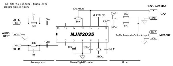
The stereo encoder consists of three main stages; pre-emphasis, digital encoder and mixer stages.
Pre-emphasis stage is achieved by using two 47K resistors and two 1nF capacitors. This helps to eliminate the noise that is produced during the FM transmission of your audio signal.
Second stage that is built around NJM2035 is a digital encoder. All of its internal blocks except for two audio amplifiers (pins 1 & 14) that act as separators are created using digital circuits. The first digital circuit is a 38KHz oscillator that is generated by using external 38KHz crystal (pin 7), 10pF capacitor (pin 6) and 100pF bypass capacitor (pin 5). Once 38KHz frequency is generated it is then buffered and divided into two 19KHz signals with a phase difference of 180 degrees. Once that is done these two frequencies are connected with two time division MPX digital alternating switchers ,one for each audio channel. Here audio channels are switched between each other with a total frequency of 38KHz. If you would be able to slow this frequency to 1Hz per second you would be able to hear that this all but a trick. During the first half of the second you would hear the left audio channel and during the second half of the second you would hear the right audio channel. Due to the fact that the channels are switched with a fast frequency of 38KHz per second our brain is unable to recognize that these channels are really switched and receives this as a continuous audio signal. At the same time another signal from the 38KHz oscillator is divided by half into 19KHz. This signal is called a PILOT tone because it will help a stereo decoder on the receiver’s part to slice the MULTIPLEX signal (mixed L and R audio channels) and separate them back into left and right audio channels.
The third stage is a mixer that consists of 33uF and 100nF capacitors and 82K and 10K resistors. The role of this circuit is to mix the multiplex subcarrier and pilot signals together. The multiplex subcarrier signal that is coming out from the pin 9 of the NJM2035 IC is the sum and difference of both left and right audio channels that are switched at 38Khz rate. The PILOT signal that is coming out of pin 8 is a 19KHz frequency that is used to distinguish what channel is currently being switched and without which stereo decoding would not be possible.
 How to Connect a Stereo Encoder to your FM Transmitter
1) First test your FM Transmitter and make sure that an audio signal is properly transmitted on your desired frequency. Once that is done turn off your transmitter and disconnect its audio inputs.
2) Connect left and right audio outputs from your audio source to the inputs of your stereo encoder.
3) Connect stereo encoder’s MPX output to your transmitter’s input (audio coax cable highly recommended).
4) Turn on your transmitter, FM receiver and audio source (making sure its audio volume is not too loud), and apply voltage supply from a single 1.5 battery cell to a stereo encoder.
5) By now you should hear a stereo sound. Adjust 50K potentiometer making sure your L-R balance is set to the middle and adjust the volume of your audio source making sure an audio signal is as clear as possible.
For more detail: NJM2035 – HI-FI Stereo Encoder / Multiplexer
- What is the required voltage supply for the stereo encoder?
The voltage supply range is 1.2V to 3.6V max. - Which IC is used in this stereo encoder?
The NJM2035 IC is used. - What component provides the stable 19kHz pilot tone?
A 38 kHz quartz crystal is used to control and generate the 19 kHz pilot tone. - How many main stages does the stereo encoder have and what are they?
There are three stages: pre-emphasis, digital encoder, and mixer. - How do you connect the stereo encoder to an FM transmitter?
Disconnect the transmitter audio input, connect audio source left/right to encoder inputs, connect encoder MPX output to transmitter input, power the encoder, then power transmitter and receiver. - What components form the pre-emphasis stage?
Two 47K resistors and two 1nF capacitors form the pre-emphasis stage. - What parts make up the mixer stage?
The mixer consists of 33uF and 100nF capacitors and 82K and 10K resistors. - What frequency range does the encoder support?
The frequency range is 20 Hz to 15 kHz. - What is the expected signal to noise ratio?
The signal to noise ratio is 67 dB. - How is channel separation achieved in the digital encoder?
The NJM2035 generates a 38 kHz oscillator divided into two 19 kHz signals and uses time division MPX digital alternating switchers to multiplex left and right channels.