
Summary of NEC Remote control decoder with PIC16F84A
The article describes decoding NEC and extended NEC IR remote protocol with a PIC16F84A microcontroller. It explains NEC timing (562.5µs pulses; 9ms header burst/4.5ms space; 32-bit message: 16-bit address, 8-bit command, 8-bit inverted command) and a simple decoding method using delay-based polling (50µs resolution) on RB0 without interrupts or timers. Code snippets validate header timing and then read 32 bits, returning false if timing bounds are violated. CCS C code for the full implementation is provided.
Parts used in the NEC Remote control decoder with PIC16F84A:
- PIC16F84A microcontroller
- IR receiver module
- Resistors (as required by schematic)
- Capacitors (as required by schematic)
- Power supply (5V)
- PCB or breadboard
- Connecting wires
- Optional LEDs for indication
The NEC protocol uses pulse distance encoding of the bits. Each pulse is a 562.5µs long with carrier frequency of 38KHz. Logic bits are transmitted as follows:
Logic 0: 562.5µs pulse burst followed by a 562.5µs space, with a total transmit time of 1125µs (562.5 x 2).
Logic 1: a 562.5µs pulse burst followed by a 1687.5µs (562.5 x 3) space, with a total transmit time of 2250µs (562.5 x 4).
The complete extended NEC protocol message is started by 9ms burst followed by 4.5ms space which is then followed by the Address and Command. The address is 16-bit length and the command is transmitted twice (8 bits + 8 bits) where in the second time all bits are inverted and can be used for verification of the received message.
NEC Protocol IR remote control decoder with PIC16F84A microcontroller:
It is easy to decode IR remote control uses NEC protocol using microcontrollers.
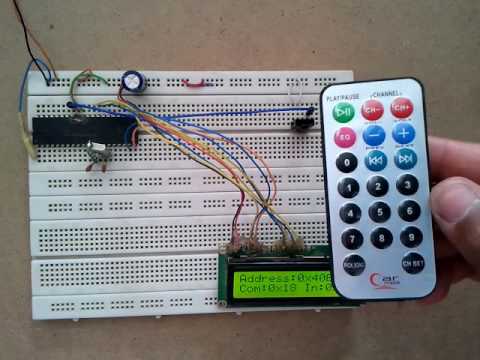
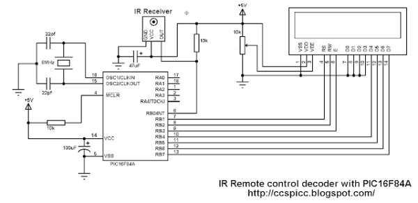
Here Microchip PIC16F84A microcontroller is used to decode IR remote controls which uses NEC and extended NEC protocol. Decoder circuit schematic is shown below. The following drawing shows an extended NEC message example.
It is easy to decode IR remote control uses NEC protocol using microcontrollers.
Here Microchip PIC16F84A microcontroller is used to decode IR remote controls which uses NEC and extended NEC protocol. Decoder circuit schematic is shown below. The following drawing shows an extended NEC message example.
NEC Protocol IR remote control decoder with PIC16F84A CCS C code:
There are different ways to decode the NEC protocol for example using CCP module and Timer, using Timer module or using port change interrupt. In this project I didn’t use any interrupt or Timer, I used delay command to make the code as simple as possible with time-out property and the code checks the IR signal with resolution of 50µs.
Programming hints:
From the decoder circuit schematic above the output of the IR receiver is connected to RB0 and when an IR signal is received RB0 pin goes from logic high (+5V) to logic low (0V).
The NEC message has 32 bits which are divided into address (16 bits), command (8 bits) and inverted command (8 bits).
The microcontroller waits until the IR receiver receives an IR signal which makes RB0 goes from logic high to logic low and the command used is:
while(input(PIN_B0));
After that a function named nec_remote_read() is called, this function checks if the received signal has NEC protocol form all the time.
The last function reads the 9ms burst using the following lines and if the pulse is more than 10ms (50µs x 200) or less than 8ms (50µs x 160) the function returns with false result which means the received signal doesn’t have NEC protocol form.
There are different ways to decode the NEC protocol for example using CCP module and Timer, using Timer module or using port change interrupt. In this project I didn’t use any interrupt or Timer, I used delay command to make the code as simple as possible with time-out property and the code checks the IR signal with resolution of 50µs.
Programming hints:
From the decoder circuit schematic above the output of the IR receiver is connected to RB0 and when an IR signal is received RB0 pin goes from logic high (+5V) to logic low (0V).
The NEC message has 32 bits which are divided into address (16 bits), command (8 bits) and inverted command (8 bits).
The microcontroller waits until the IR receiver receives an IR signal which makes RB0 goes from logic high to logic low and the command used is:
while(input(PIN_B0));
After that a function named nec_remote_read() is called, this function checks if the received signal has NEC protocol form all the time.
The last function reads the 9ms burst using the following lines and if the pulse is more than 10ms (50µs x 200) or less than 8ms (50µs x 160) the function returns with false result which means the received signal doesn’t have NEC protocol form.
while((input(PIN_B0) == 0) && (count < 200)){
count++;
delay_us(50);}
if( (count > 199) || (count < 160))
return false;
The 4.5ms space is checked as the 9ms burst with small differences:
while((input(PIN_B0)) && (count < 100)){
count++;
delay_us(50);}
if( (count > 99) || (count < 60))
return false;
After that the microcontroller starts reading the 32 bits and keeps checking of NEC protocol form.
The following code is the complete CCS PIC C code written with compiler PCWHD version 5.051.
Read more: NEC Remote control decoder with PIC16F84A
- What is the pulse length used in NEC protocol?
Each pulse burst is 562.5µs long with a 38kHz carrier. - How is logic 0 and logic 1 encoded in NEC?
Logic 0 is 562.5µs burst + 562.5µs space; Logic 1 is 562.5µs burst + 1687.5µs space. - What is the header for an extended NEC message?
A 9ms burst followed by a 4.5ms space starts the message. - How many bits are in the NEC message and how are they arranged?
The message is 32 bits: 16-bit address, 8-bit command, and 8-bit inverted command. - Which PIC pin is used for the IR receiver input in the project?
The IR receiver output is connected to RB0. - Does the project use interrupts or timers to decode the signal?
No, it uses delay-based polling with 50µs resolution and no interrupts or timers. - How does the code verify the 9ms header pulse?
It measures the low pulse in 50µs steps and returns false if the count is outside 160–199 (8ms–10ms). - How is the 4.5ms space validated?
It measures the high space in 50µs steps and returns false if the count is outside 60–99 (3ms–5ms approximately). - What compiler was used for the provided CCS C code?
The code was written for CCS C compiler PCWHD version 5.051.
