Introduction:
This describes my original design dual channel quantizer inspired by Chris List’s ARP Style CV Quantizer design. My new implementation is an intelligent design that exploits the programmability of a Microchip PIC16F84. It will quantize voltages in 1/12 volt (semitone) or 1 volt (octave) steps from –10V to 10V. Quantization time is about 2ms per channel. Octave switches allow the user to select between semitone or octave quantization.
On a per channel basis, this design uses a digital-to-analog converter (DAC), a comparator, and a sample/hold to continuously quantize an analog signal. A suitably programmed PIC drives the quantization process. The addition of a second comparator and sample/hold is all that is needed to get a second channel. Even more channels can be added at the expense of PIC pins and conversion interval per channel. The DAC is multiplexed among all channels.
The design was built to the MOTM format using the MOTM-000-A1 DIY breadboard with power cable and mounting bracket from Synthesis Technology. I also purchased the MOTM-1UB blank 1U panel for the front panel. Other parts were obtained from my own personal stock, Mouser, and Digikey.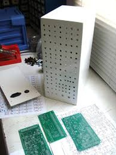
Design Discussion:
See the schematic and source code to follow the design discussion. The circuit engine is a Microchip PIC16F84 microcontroller (U1) clocked at 10MHz and an MP7542 12 bit DAC (U2). Op amp U3B converts the current output of the DAC to a voltage output. Op amp U3A allows the trimming of the zero voltage point and control voltage scale. The components used around U3A were selected to achieve standard 1V/octave CV scaling. Channel 1 sample/hold is built around U4A, C18, and U5A. Channel 2 sample/hold is built around U4B, C19, and U5B. Resistor R5 provides some slew limiting to keep down noise. Channel 1 comparator is U8. Channel 2 comparator is U9. The 100W and 180KW resistors around the comparators provide about 8mv of hystersis to reduce comparator chatter due to noise. The PIC and DAC are powered by 5V. This voltage is supplied by U6. The DAC and zero/scaling circuits require a clean 12V reference. This voltage is supplied by U7. Diode D1 limits the maximum voltage at the PIC input RA4 to 5V. The internal protection diode limits the maximum voltage at the PIC input RB3 to 5V. Resistors R9 and R13 limit the current through internal and external limiting diodes. Resistors R8 and R12 provide pull-up voltage to the open collector outputs of the comparators.
The design is a two channel design in which both channels CVs are quantized repeatedly and in order. A complete dual channel quantization cycle begins with the PIC executing an 8 bit binary search cycle to find the digital value of the control voltage, CV1, at the channel 1 comparator. This is essentially a digital to analog conversion process. The channel 1 sample/hold is set to hold during the search cycle. When the search cycle is complete, the channel 1 sample/hold is set to sample the DAC output for a brief time to allow the hold capacitor to charge. After the sample time, the PIC executes a quantization cycle on channel 2 similar to that of channel 1.
A 12 bit DAC was chosen to achieve the accuracy needed for VCO control voltages. Only the 8 most significant bits are used. Doing this, 12 bit accuracy is achieved in an 8 bit application. The MP7542 was selected because I have many on hand. Any comparable 12 bit (or better) DAC can be used with the appropriate software changes.
The design also uses an octave switch to use octave (MOD12) quantization for control voltages. Closing the octave switch for a given channel selects octave quantization otherwise semitone quantization is used. This is a simple math function performed in software. This would suggest that any quantization scales could be implemented with the appropriate software changes. This is exactly what the Doepfer A-156 Dual Quantizer does.
The PIC is clocked at the maximum rate of 10MHz for the part I used. It may be clocked at lower frequencies but software changes may be needed so as not to adversely affect the conversion interval per channel. The DAC is loaded in about 6ms at 10MHz. The DAC requires a 40ms settling period after loading the output register. This time is consumed in the PIC software in a timed loop that does nothing. The sample time is set to 1ms. This time is also consumed in the PIC software in a timed loop that does nothing. The sample time consumes most of the conversion cycle time.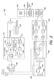
Construction:
There were no unusual construction circumstances. As usual, digital and analog grounds should be kept separate. Digital circuitry should be located as far from analog circuitry as possible. Sample/hold layout should be kept as tight as possible. All IC power pins should be bypassed by .1m F capacitors.
All ICs used are DIP packaged with the exception of the voltage regulators. The voltage regulators are packaged in the TO-92 low power type packages. The PIC can be reprogrammed and, therefore, is socketed using a high quality 18 pin DIP socket with gold plated contacts. The DAC is socketed in case I want to hand select the DAC for accuracy. All other components are soldered directly to the board. All resistors are 1/8W 1% metal film. All 1% resistors were chosen to make parts ordering simpler. Resistors R1, R2, and R3 are required to be 1% tolerance. All other resistors may be 5% or 10% parts. Bypass capacitors are .1m F ceramic disc. The sample/hold capacitors are 1000pF polystyrene which is critical for droop free and accurate output. Potentiometers VR1 and VR2 are linear taper trimmers mounted on the board. Octave switches S1 and S2 are mounted on the panel. Jacks J1 through J4 are also mounted on the panel.
For more detail: MOTM Compatible Dual Channel Quantizer