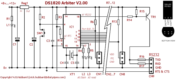
Summary of DS1820 Arbiter V2.00 Schematic / Parts List
This article details the RS232 connection notes, component specifications, and testing procedures for a DS1820 Arbiter project. It outlines wiring requirements for D-type connectors, lists specific resistors, capacitors, ICs, and connectors needed, and explains LED status indicators. The guide also covers PIC microcontroller programming and provides step-by-step instructions for verifying hardware functionality with a PC terminal.
Parts used in the DS1820 Arbiter:
- R1, 4, 5, 16, 17 (220R)
- R2, 14, 15 (2k2)
- R3, 18 (10k)
- R6..13 (4k7)
- C1,2 (47µF, 16V)
- C3 (0.01µF)
- C4,5 (15pF)
- REG1 (7805 5volt regulator)
- IC1 (PIC16L84-04/P or PIC16F84-04/P)
- SW1 (Momentary Push Button reset)
- L1, 2 (LED Red)
- L3 (LED Green)
- CN1..8 (3 way PCB mounted connector)
- CN9 (4 way PCB mounted connector)
- TR1 (BC212 PNP transistor)
- XT1 (2.4576 MHz)
- Misc items including power block, cable, and silicone rubber
RS232 Connection Notes
See the RS232 reference to determine the wiring for either a 9-way or 25-way female D Type “sub-miniature” connector.
RTS and CTS are connected together. RXD is used to steal a negative supply.
You may have to connect DSR and DCD to DTR if you are using the Arbiter hardware with other software. This connection is not required with HotBox or the NT service tempscv.exe.
| Reference | Description |
| R1, 4, 5, 16, 17 | 220R |
| R2, 14, 15 | 2k2 |
| R3, 18 | 10k |
| R6..13 | 4k7 (Fit as required) |
| C1,2 | 47µF, 16V (Note polarity) |
| C3 | 0.01µF |
| C4,5 | 15pF |
| REG1 | 7805 5volt regulator (Note pin out) |
| IC1 | PIC16L84-04/P (Or PIC16F84-04/P) See notes below |
| SW1 | Momentary Push Button (reset) |
| L1, 2 | LED Red (Note polarity) |
| L3 | LED Green (Note polarity) |
| CN1..8 | 3 way PCB mounted connector. Up to 8 DS18B20s may be connected to each connector. (Fit as required) |
| CN9 | 4 way PCB mounted connector. |
| TR1 | BC212 – or any general purpose PNP switching transistor (Check the pin out!) |
| XT1 | 2.4576 MHz |
| Misc | Power block (9v 100mA), power connector, up to 64 DS18B20s, cable, silicone rubber, sleeveing, mating connectors for CN1..9, RS232 female connector |
LED’s – what they indicate
L1 steady – power on
L2 flashing once a second – firmware is running
L3 lit – A DS1820 is being polled
If RTS drops, the controller will stop polling and turn off L2 and L3.
Testing Notes
Disconnect from PC and disconnect DS1820 probes. L1 should be on, L2 flashing.
Connect a DS1820 probe. L3 should flick on once every 5 seconds. Additional probes can be connected “hot”. (Each single wire bus is scanned every 5 seconds, additional devices will be recognized when connected.)
Connect to PC. L2, L3 out. Use (hyper) terminal set to 19200, 8 data, no parity, 1 stop bit. When “connected” (RTS/CTS asserted) L2, L3 should revert to flashing. Check for data frames.
PIC16F84-04/P Notes
PICS are general purpose micro controllers, manufactured by Microchip Technology. They are popular devices for hobbyists/ hackers/ nerds/ electronic geniuses and can be used for all sorts of purposes.
 PIC’s come in different packages, speeds, voltage range, temperature range and power dissipation. The 16F84-04/P is the “entry level” version. Its siblings will probably work in the circuit, but I haven’t tested all of them. Avoid /SO devices – unless you’ve laid out your board for surface mount!
A 16F84-04/P device needs programming before it can do anything useful. The PIC Source .asm file needs to be compiled. The generated .hex file will contain the program instructions and configuration bits. The .hex file is read by the programmer and is used to “blow” the device. A 16F84-04/P can be reprogrammed many times.
For more detail: DS1820 Arbiter V2.00 Schematic / Parts List
- How should RTS and CTS be connected?
RTS and CTS are connected together. - What is the purpose of RXD in this circuit?
RXD is used to steal a negative supply. - When must DSR and DCD be connected to DTR?
This connection is required if using Arbiter hardware with other software, but not with HotBox or NT service tempscv.exe. - What does a steady L1 LED indicate?
A steady L1 indicates that power is on. - How often is the single wire bus scanned?
The single wire bus is scanned every 5 seconds. - What happens to L2 and L3 when RTS drops?
The controller stops polling and turns off L2 and L3. - What terminal settings are required to connect to the PC?
Use hyper terminal set to 19200 baud, 8 data bits, no parity, and 1 stop bit. - Can additional probes be connected while the system is running?
Yes, additional probes can be connected hot and will be recognized during the next scan. - Which PIC package types should be avoided unless using surface mount boards?
Avoid /SO devices unless you have laid out your board for surface mount. - What file type contains the program instructions for the PIC?
The generated .hex file contains the program instructions and configuration bits.