One day, looking for interesting schemes with light effects to construct, came across this wonderful effect. Quite liked the idea but did not know how to accomplish is, until one day found the way. Subsequently construct my own mirror that had to not only try out my skills in electronics but and processing of wood (to create a frame). In this article I will share all the difficulties faced by all subtleties and found that while it is constructed. Many experimented with different windows and mirrors until desired effect is achieved. To facilitate lovers of electronics and in particular light effects as I would describe it as detailed. I will apply the schemes and boards and everything that I constructed. Of course I designed mirror frame on my taste and choice, but everyone has a different look beautiful, and you can use your imagination instead of myne in his own choice. I guess that schemes are found here will facilitate the development of such a mirror to your liking.
You can buy kit for assembling and see another interesting projects in my website: www.kukata86.com
Step 1: What is the mirror “Tube”?
The device is constructed as a mirror that creates the optical illusion of a tunnel formed by the LEDs. The effect is quite interesting and very hot right lately. Its true effect observed especially impressive when viewed in a dark room or in a room with not very strong light (then you really see the entire depth of the tunnel and the effect of changing colors), a during daylight hours drive takes the role of a simple mirror .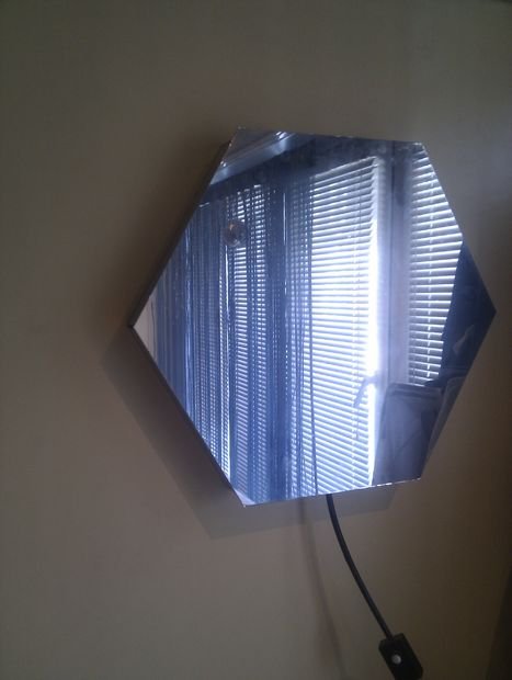
Step 2: How is made and how it creates the illusion?
The device consists of a frame and two electronic units.
- Some wood frame (size and shape of your choice) on the inside and countries are LEDs. The rear of the frame is a regular mirror and the front – glass with mirror properties. Thus the light emitted by the LEDs is reflected in the rear mirror and the windshield with mirror properties and that multiple internal reflection creates the illusion of a tunnel. The ability to see with my own eyes the effect comes from the glass with mirror properties repeatedly missed out internal reflection, and this allows us to glimpse what is happening between the two glasses. This gives the illusion of multiple meter tunnel from the device until between 5-10 cm thick
- Controller, which sets different modes of RGB light boards, control the LEDs. This controller manages separate each color of RGB LEDs (red, green, blue), thus achieving different shades of colors formed by combining these three colors.
- Another important element is the board with RGB LEDs or LED Strips (I designed the 3 different sizes of boards / 8.7 cm X 1.5 cm X 0.7 cm / / 19.5 cm X 1.5 cm X 0.7 cm / / 39 cm X 1.5 cm X 0.7 cm / whose number of LEDs also depends on appropriate / 4 / / 9 / and / 19 / LED) boards can be combined so that they are comfortable length for your purposes. When use LED strips, keep in mind that it is cut in a certain size, amount mostly through 3 LEDs.
You can buy kit for assembling and see another interesting projects in my website: www.kukata86.com
Step 3: Construction of mirror “Tube”
Step 4:
Each inner sides will work out dimensions of 40 cm (in order to be able later to mount LED board size 39 cm)
I worked six equal square battens with dimensions 5 cm X 5 cm X 20 cm.
Step 5:
Step 6:
IMPORTANT!
Remember to follow the length of the plateau of the trapezoid. As I mentioned in my case it is 40 cm so I can mount the PCB with LEDs with a length of 39 cm. In your case it may be a different size but, comply with what length card or combination of boards to use. If you use LED Strip is not required to comply with such factors, only inside tour of the frame.
Gathering all the shingles to each other on the mirror frame shape – regular hexagon.
Step 7:
Each of them has an internal groove which to place the board with LEDs sizes / 39 cm x 1.5 cm /. Flap is 7 mm deep (as the height of the LED board). If you use LED Strip, flap is not binding or it may be quite shallow – about 1 mm (almost enough to hide the double sided tape on the back of the strip), but not deep enough to hide the LEDs.
Edge to the back of the mirror can save it if you find a better way to attach the mirror, but in any event not glued to the frame because the windshield will be stuck in this case if you need to replace or repair any of boards with LEDs opening the mirror becomes impossible.
Step 8:
Once you paint them all with plain black spray glued with glue all 6 mounting rails to form a hexagon. Boards tucked in groove provided them solder each other with short wires observing the colors of buses R with R, G with G, B with B and + with +. From one of the sides of the hexagon idrilled hole to lead the LED power cable circuits which will later connect to the controller. If you use LED Strip simply glue the runners made earlier for this purpose and bring out the frame cables.
View of adhesive frame without glass – front
In yellow visible groove provided for LED circuits.
Step 9:
View of frame – rear
In yellow visible groove provided for LED panels and “nest” provided a mirror on the back of the frame.
Step 10:
I ordered to a glass company to cut a hexagon of my mirror glass for glass packs (without excessive color / brown or green /). He ordered a glass 5 mm larger in diameter than the outside of the frame to have a good overlap with the side mirrors that will put more later.
I glued glass mirror mounting adhesive on the front of the frame
View of mirror – front:
Step 11:
View of mirror – rear
In the mirror glass side of the glass is noticeably better properties mirror (mirror coating is applied on the country) on the other. Experimental realized that this was it’s better to be on the inside of the mirror to the LEDs. To reinforce mirror properties and took the outside mirror foil for car windows and taped on the outside of the glass. This reinforced the ability to look at myself in the mirror during the day and svetodeodite properties to reflect better at night.
And mirror cut to size appropriate to enter the nest that predicted. Once I put it in its cradle on the edge between the glass and frame it taped with duct tape. Thus strengthened it does not fall and I opened it without difficulty have an ace.
Step 12:
Before you close the mirror finally cleaned both windows so that no dust to close between the two glasses. Emphasize the fact that visible dust is not visible during the day can be seen very clearly in the mirror tunnel.
Finally, cut out five mirrors the size of the external frame pages and pasted them from outside the country and to hide the visible wooden part. At the top of the frame does not put a piece of glass as there put two D shaped brackets which attached the mirror hanging on the wall. Side mirrors have given quite finished mirror and made really good-looking aesthetic.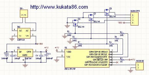
Step 13: Preparation and assembly of LED boards
I designed three types of LED boards.
- 8.7cm % 1.5cm % 0.7cm – 4 LEDs
- 19.5cm % 1.5cm % 0.7cm – 9 LEDs
- 39cm X 1.5cm % 0.7cm – 19 LEDs
Number of LEDs of each depends on the length her LED boards can be combined according to your needs and depending on the chosen framework, but their number should not exceed 300. This is the maximum count that mirror’s controller (discussed below) can handle without risking damage.
You can buy kit for assembling and see another interesting projects in my website: www.kukata86.com
Step 14:
Led Board 8.7cm % 1.5cm – 4 LEDs
Board Top-PDF
Board Top with white masK-PDF
Board Bottom (mirrored)-PDF
Led Board 19.5cm % 1.5cm – 9 LEDs
Board Top-PDF
Board Top with white mask-PDF
Board Bottom (mirrored)-PDF
Led Board 39cm X 1.5cm – 19 LEDs
This board is divided into two parts. To be printed in real size is divided into two A4 sheets.
Board Top:
Part 1-PDF
Part 2-PDF
Board Top with white mask:
Part 1-PDF
Part 2-PDF
Board Bottom (mirrored):
Part 1-PDF
Part 2-PDF
The accompanying drawings boards are life-sized. For the preparation of PCB important to use methods of amateur laser printer or photo-method.
You can buy kit for assembling and see another interesting projects in my website: www.kukata86.com
In the attached file the top of the board is flipping to be suitable for carrying laminated after printing.
For more detail: Mirror “Tube” – LED Optical illusion