Summary of LTC Design Notes: Micropower Isolated Flyback Converter with Input VoltageRange from 6V to 100V
The LT8300 simplifies isolated flyback converter design by integrating a 150V DMOS switch, internal compensation, and primary-side sensing. This eliminates opto-couplers, reduces component count to five, and achieves high efficiency with ±1% load regulation across a 6V to 100V input range.
Parts used in the LT8300 Flyback Converter:
- LT8300 integrated circuit
- Transformer
- Output diode
- Soft-start capacitor
- Five external components (general)
Introduction
Flyback converters are widely used in isolated DC/DC applications because of their relative simplicity and low cost compared to alternative isolated topologies. Even so, designing a traditional flyback is not easy—the transformer requires careful design, and loop compensation is complicated by the well known right-half plane (RHP) zero and the propagation delay of the opto-coupler.
Linear Technology’s no-opto flyback converters, such as the LT3573, LT3574, LT3575, LT3511, and LT3512, simplify the design of flyback converters by incorporating a primary-side sensing scheme and running the converter in boundary mode. The LT8300 high voltage monolithic isolated flyback converter further simplifies flyback design by integrating a 260mA, 150V DMOS power switch, an internal compensation network and a soft-start capacitor. The LT8300 operates with input supply voltages from 6V to 100V and delivers output power of up to 2W with as few as five external components.
The LT8300 operates in boundary mode and offers low ripple Burst Mode operation, enabling the design of converters that feature high efficiency, low component count and minimal power loss in standby.
Simple and Accurate Primary-Side Voltage Sensing
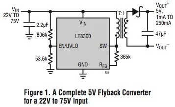
The LT8300 eliminates the need for an opto-coupler by sensing the output voltage on the primary side when the output diode current drops to zero during the primary switch-off period. This greatly improves the load regulation since the voltage drop is zero across the transformer secondary winding and any PCB traces. This allows an LT8300-based flyback converter to produce ±1% typical load regulation at room temperature. Figure 1 shows the schematic and Figure 2 the load regulation curves of a flyback converter with a 5V output.
For more detail: LTC Design Notes: Micropower Isolated Flyback Converter with Input Voltage Range from 6V to 100V
- Why are traditional flyback converters difficult to design?
The transformer requires careful design, and loop compensation is complicated by the right-half plane zero and opto-coupler propagation delay. - How does the LT8300 eliminate the need for an opto-coupler?
It senses the output voltage on the primary side when the output diode current drops to zero during the switch-off period. - What is the typical load regulation of an LT8300-based converter at room temperature?
It produces ±1% typical load regulation because the voltage drop is zero across the transformer secondary winding and PCB traces. - What is the input supply voltage range for the LT8300?
The device operates with input supply voltages from 6V to 100V. - What is the maximum output power delivered by the LT8300?
The converter delivers output power of up to 2W. - How many external components are required for an LT8300 design?
It can be designed with as few as five external components. - What mode of operation does the LT8300 use to achieve low ripple?
It operates in boundary mode with low ripple Burst Mode operation. - Does the LT8300 integrate a power switch?
Yes, it integrates a 260mA, 150V DMOS power switch.