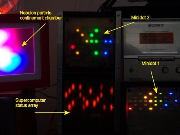
Minidot 2 – The holoclock
Well maybe holoclock is a little bit inaccurate….it does use holographic dispersion film on the front to give a bit of depth.
Basicaly this instructable is an update to my previous Minidot located here:
http://www.instructables.com/id/EEGLXQCSKIEP2876EE/
and re-using a lot of code and circuitry from my Microdot located here:
http://www.instructables.com/id/EWM2OIT78OERWHR38Z/
EagleCAD files and Sourceboost code is included in the zip files attached.

Why? The previous Minidot was overly complex, from the Microdot I learned how to do an RTC on a PIC using only a 32.768 crystal and didn’t need to use a special RTC chip. Also I wanted to get rid of the display chips from the previous Minidot. So now there is only a power regulator chip and a PIC16F88….just two chips.
The other reasons for an update were my Minidot was getting a bit un-reliable because of the seperate switch board and I wanted a soft fade between dot patterns as well as some sort of ambient light sensor to dim the display at night. The other Minidot was fixed brightness, and illuminated a room at night.
The device was constructed with the aid of the EagleCad software package and Sourceboost compiler. You’ll need to have some experience with electronics and programming PIC controllers to start this project. Please note this isn’t an instructable on either electronics or PIC programming, so please keep questions relevant to the Miniclock design. Refer to the instructables above or many other instructables on this site for advice on using EagleCad or programming PICs.
So here it is…..Minidot 2, The Holoclock……or Minidot The Next Generation………….
The circuit
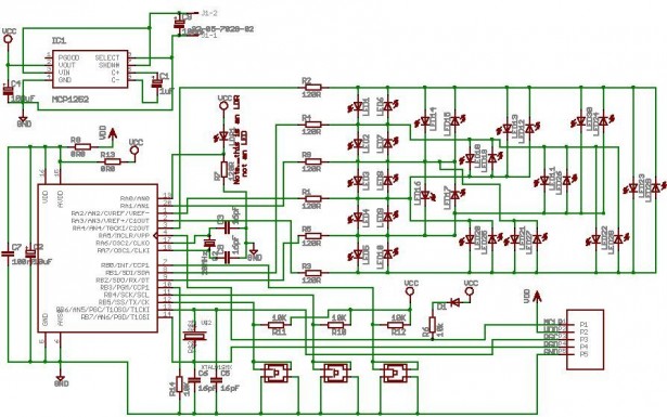
A 20Mhz crystal has been added to the Microdot circuit to clock the PIC much faster, this allows the array to be scanned faster and enables the implementation of a dimming algorithm. The dimming algorithm was very important to getting a cross pattern fade and ambient light function to work. This would have been impossible with the Microdot, because of the slower clock speed as some scan cycles needed to be spent on dimming. See next section for a description of the Dimming functionality.

The other things to note are the use of a MCP1252 charge pump regulator to supply 5V, my favourite chip at the moment. If you modified the circuit you could use a plain old 7805……I just have a number of these handy chips hanging around.
I’ve now moved the switches to the front, saves fiddling round the back of the clock after power dropouts to reset the time and now everything is only one PCB….no cabling issues.
Also of note is the inclusion of an LDR. This is used in a voltage divider which is sensed by the A/D pin on the PIC. When the PIC senses the ambient light level is low (ie night time) the dimming algorithm keeps the charlieplex array dark for more cycles than when the light level is high. I couldn’t find an LDR symbol in the Eaglecad library, so I just used an LED symbol…..don’t be fooled it’s an LDR. See actual picture of the PCB below.
One thing to note when using multi-coloured LEDs in a charliplex array. You need to make sure the forward voltage of the LEDs are more or less the same. If not, then stray current paths may occur and multiple LEDs will light. Thus using 5mm or higher power LEDs for this configuration will not work as there is usually quite a difference between the green/blue LEDs and the red/yellow LEDs. In this case I used 1206 SMD leds and high efficiency green/blue LEDs in particular. The forward voltages were not an issue here though. If you wanted to use a mix of green/blue and red/yellow higher power LEDs in a charlieplex array you’d need to seperate out the different colours into two charliplex arrays.
There are numerous explanations of charlieplexing that can be googled……I’ll not go into details here. I’ll leave it to you to do some research.
(Press the little ‘i’ icon in the corner of the pic below to see a larger version)
The dimming algorithm – charliplexed pulse width modulation
As mentioned earlier, I wanted to have the different dot patterns for the time fade smoothly rather than jerking from one pattern to another.
