Summary of Microchip PIC Microcontrollers
This article details the implementation of In-Circuit Serial Programming (ICSP) for Microchip PIC microcontrollers. It outlines the necessary 5-pin connections, noise filtering circuits for the MCLR pin, and specific voltage requirements for VDD and VPP. The text also discusses hardware interfaces using headers or bed-of-nails jigs, troubleshooting common programming issues like marginal VPP levels in older socket modules, and verifying signal waveforms with an oscilloscope to ensure compliance with rise time specifications.
Parts used in the ICSP Implementation Project:
- VDD Pin
- VPP (MCLR) Pin
- SCLK (RB6)
- SDAT (RB7)
- GND Pin
- 1K Resistor
- .1 uF Capacitor
- Surface Mount Chip Devices C1 and C2
- 5 Pin Header (Molex)
- Bed of Nails Jig with Spring Loaded Probes
- Microchip ICSP Socket Module
- PRO MATE II Programmer
- LEDs for Status Indication
- 5.6 Ohm Resistor
- Digital Storage Scope
- Op-Amp based VPP Buffer
- Reverse Polarity Protection Diode D1
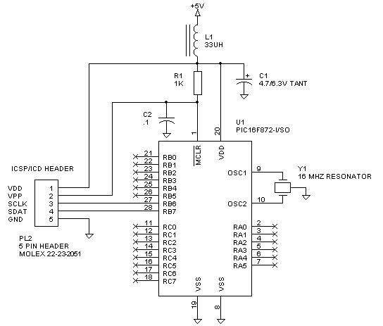
Implementing ICSP requires connections to a minimum of 5 processor pins: VDD, VPP (also MCLR\), SCLK (on RB6), SDAT (on RB7), and GND. VDD and GND are straightforward. In most applications, it is best to dedicate RB6 and RB& for SCLK and SDAT. This avoids potential complications when these signals are used during programming. Microchip shows a suggested circuit for MCLR\ involving a RC network and diode. Since the MCLR\ pin is quite noise sensitive (sub microsecond noise glitches can cause a reset), we suggest an alternate circuit as shown in Figure 1. The 1K resistor and .1 uF capacitor provide generous filtering and greatly improve EMI susceptibility in harsh industrial or automotive environments. Figure 1 shows a suggested 5 pin header that also works with the Microchip In-Circuit Debugger (ICD) for FLASH devices. Note that C1 and C2 are both surface mount chip devices that should be mounted right at the PIC. The 5 pin ICSP/ICD header should be in close proximity to the PIC. The suggested 5 pin Molex header is inexpensive and readily available. The header is used for pilot production. A “bed of nails” type of jig with spring loaded probes can be fabricated for production use as shown in Figures 4 and 5. At that point, the Molex header is left off, and the probes contact the pads on the PCB.
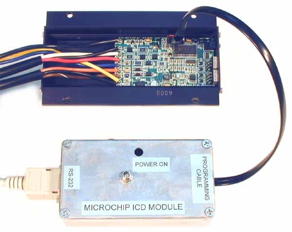 Figure 2 shows the schematic for a suggested ICSP programmer interface between an ICSP enabled product and a Microchip ICSP socket module installed on a PRO MATE II programmer. LEDs indicate pass/fail status, VPP, and VDD. The VPP and VDD LEDs are useful for quickly diagnosing shorts. Programming starts when the GO button is pressed and is complete when either the PASS or FAIL LED illuminates. Successful programming requires that VDD and VPP maintain precise levels (typically 4.75V to 5.25V for VDD and 12.75V to 13.25V for VPP). VPP must have a maximum rise time of 8 usec (mistakenly printed as msec on some data sheets). Transmission line effects along the cable from the ICSP socket module to the programmer interface and continuing to the PIC board must be taken into account. Don’t take anything for granted! Observe the actual VDD and VPP waveforms at the PIC with a good digital storage scope. We found that the 5.6 ohm resistor shown in Figure 2 was required to minimize ringing on the VPP signal. Actual ICSP signal waveforms for a 12C672 are shown in Figure 3. VDD is on channel 1 and VPP is on channel 2. The 50 usec/div time base was chosen to display the rising edge of both signals. You should also observe the rising edge of VPP with a faster time base to verify the 8 usec maximum rise time requirement. VDD rise time is not critical and will depend on total bypass capacitance on the +5V supply rail. Note that VPP rises before VDD for the 12C672. Some Microchip parts require stable VDD before VPP rises. Refer to the Microchip programming specifications for details.
 Early Microchip ICSP socket modules had a marginal VPP voltage level just below the required 12.75V. The problem was caused by an op-amp based VPP buffer that used a 15V power supply. The VPP buffer just couldn’t swing high enough while sourcing current. We found the problem and suggested a fix to Microchip that involved jumpering out the power supply reverse polarity protection diode (D1) on the socket module. A newer socket module with the diode jumpered is shown in Figure 6. Check your socket module. If the diode has not been replaced with a zero ohm jumper, just solder a short wire across it. Without this fix, any parts programmed are marginal at best.
For more detail: Microchip PIC Microcontrollers
- What pins are required for implementing ICSP?
A minimum of 5 processor pins are needed: VDD, VPP (also MCLR), SCLK on RB6, SDAT on RB7, and GND. - How can EMI susceptibility be improved in harsh environments?
Using a 1K resistor and .1 uF capacitor in the MCLR circuit provides generous filtering to improve EMI susceptibility. - Where should capacitors C1 and C2 be mounted?
C1 and C2 must be surface mount chip devices mounted right at the PIC microcontroller. - What is the maximum rise time requirement for the VPP signal?
VPP must have a maximum rise time of 8 microseconds to meet programming specifications. - Why is a 5.6 ohm resistor included in the schematic?
The 5.6 ohm resistor is required to minimize ringing on the VPP signal caused by transmission line effects. - How do you verify if the VPP rise time meets requirements?
You should observe the rising edge of VPP with a faster time base on a digital storage scope to verify the 8 usec limit. - What was the cause of marginal VPP levels in early socket modules?
The problem was caused by an op-amp based VPP buffer using a 15V power supply that could not swing high enough while sourcing current. - What fix resolves the marginal VPP issue in older socket modules?
The fix involves jumpering out the power supply reverse polarity protection diode D1 by soldering a short wire across it. - When does successful programming occur during the process?
Programming is complete when either the PASS or FAIL LED illuminates after pressing the GO button. - Do all Microchip parts require stable VDD before VPP rises?
No, some parts require stable VDD before VPP rises, so you must refer to the specific Microchip programming specifications.