Summary of Measuring Temperature using LM74 temperature sensor by Texas Instruments and Pic18f452 Microcontroller
This article describes interfacing the LM74 temperature sensor with a PIC18F452 microcontroller using SPI communication. The LM74 sensor provides a 16-bit digital temperature reading with a resolution of 0.0625°C, operating in slave mode between -55°C and +150°C. The PIC18F452 uses dedicated SPI pins (SDO, SDI, SCK, SS) configured via SSPSTAT and SSPCON1 registers to communicate with LM74. The project includes a circuit and C code for reading temperature data and displaying it on an LCD. SPI transactions involve sending dummy data to receive temperature bytes, which are processed and shown in Celsius on the LCD.
Parts used in the LM74 Temperature Sensor Interfacing Project:
- LM74 temperature sensor (Texas Instruments)
- PIC18F452 microcontroller
- Hitachi-type LCD display
- Resistors (for pull-ups and LCD interface)
- Crystal oscillator 4 MHz
- Connecting wires and breadboard/PCB
In this post i am going to interface LM74 temperature sensor with Pic18f452 microcontroller. LM74 is a temperature sensor by Texas Instruments. It comes with an SPI (Serial Peripheral Interface) interface. You can operate it in SPI (Serial Peripheral Interface) mode. A processor/microcontroller can read temperature reading from LM74 at any time. LM74 provides resolution of up to 0.0625 degree Centigrade. It can operate between -55 degree to +150 degree centigrade. It works only as slave in a system. When interfaced with processor / microcontroller in SPI mode it can only be a slave to a host.
I assume that you are already familiar with the SPI interface. If not then first took some tutorials on SPI (Serial Peripheral Interface) interface before going through this project.
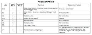
LM74 Temperature Sensor Pin Out
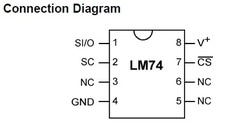
SI/O is Slave input/output. All the commands, control signals and data, travels in and out of the sensor from this pin.Data is clocked out from the sensor on the falling edge of the serial clock (SC), while data is clocked in on the rising edge of SC. A complete transmit/receive communication will consist of 32 serial clocks. The first 16 clocks comprise the transmit phase of communication, while the second 16 clocks are the receive phase. SC is Slave clock. In SPI mode clock is essential to carry out the task.
LM74 Temperature Sensor Registers
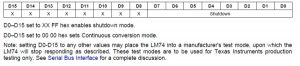
LM74 Temperature Sensor Configuration Register
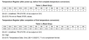
LM74 Temperature Register
Note: On first power up LM74 will output arbitrary data don’t worry its for the first time power up. Then its start working perfectly.
LM74 Manufacturer’s Device ID Register
SPI communication with Pic8f452 Microcontroller
- Serial Data Out (SDO) – RC5/SDO
- Serial Data In (SDI) – RC4/SDI
- Serial Clock (SCK) – RC3/SCK
- Slave Select (SS) – RA5/SS
Three registers are associated with SPI communication. To carry out successful SPI communication we have to configure them correctly.
SSPSTAT SPI status register
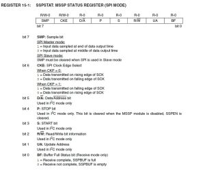
SSPCON1 SPI Control Register
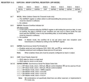
SSPBUF (Serial Receive and Transmit Register)
Project Circuit Diagram
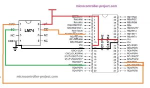
LM74 temperature sensor by Texas instruments interfacing with Pic18f452 Microcontroller
Project Code
| #include <p18f452.h> | |
| #include <stdio.h> | |
| #define _XTAL_FREQ 4000000 //Frequency of Oscillator 4MHz | |
| #define RD5 LATDbits.LATD5 //Define as PORT D Pin 6 | |
| #define RD5Tris TRISDbits.TRISD5 //Define as TRISD Pin 6 | |
| #define RD6 LATDbits.LATD6 //Define as PORT D Pin 6 | |
| #define RD6Tris TRISDbits.TRISD6 //Define as TRISD Pin 6 | |
| #define RD7 LATDbits.LATD7 //Define as PORT D Pin 7 | |
| #define RD7Tris TRISDbits.TRISD7 //Define as TRISD Pin 7 | |
| #define SS LATAbits.LATA5 //Define as PORT A Pin 4 as SS Slave Select | |
| #define SSTris TRISAbits.TRISA5 //Define as TRISA Pin 4 | |
| #define SDO LATCbits.LATC5 //Define as PORT C Pin 5 as Slave data out | |
| #define SDOTris TRISCbits.TRISC5 //Define as TRISC Pin 5 | |
| #define SDI LATCbits.LATC4 //Define as PORT C Pin 4 as Slave data in | |
| #define SDITris TRISCbits.TRISC4 //Define as TRISC Pin 4 | |
| #define SCK LATCbits.LATC3 //Define as PORT C Pin 3 as CLock | |
| #define SCKTris TRISCbits.TRISC3 //Define as TRISA Pin 3 | |
| void delay(unsigned int time) //Time delay function | |
| { | |
| unsigned int i,j; | |
| for(i=0;i< time;i++) | |
| for(j=0;j< 5;j++); | |
| } | |
| //Function for sending values to the command register of LCD | |
| void lcdcmd(unsigned char value) | |
| { | |
| PORTB=value; | |
| RD6= 0; //register select-rs | |
| RD5 = 0; //read-write-rd | |
| RD7 = 1; //enable-e | |
| delay(50); | |
| RD7=0; //enable-e | |
| delay(50); | |
| } | |
| //Function for sending values to the data register of LCD | |
| void display(unsigned char value) | |
| { | |
| PORTB=value; | |
| RD6= 1; //register select-rs | |
| RD5= 0; //read-write-rd | |
| RD7= 1; //enable-e | |
| delay(500); | |
| RD7=0; //enable-e | |
| delay(50); | |
| } | |
| //function to initialize the registers and pins of LCD | |
| //always use with every lcd of hitachi | |
| void lcdint(void) | |
| { | |
| delay(15000); | |
| display(0x30); | |
| delay(4500); | |
| display(0x30); | |
| delay(300); | |
| display(0x30); | |
| delay(650); | |
| lcdcmd(0x38); //5×7 Font text will be displayed on lcd | |
| delay(50); | |
| lcdcmd(0x0C); //Display on Cursor off | |
| delay(50); | |
| lcdcmd(0x01); //Clear LCD (DDRAM) | |
| delay(50); | |
| lcdcmd(0x06); //Entry Mode | |
| delay(50); | |
| lcdcmd(0x80); //Put Cursor at first line first character space | |
| delay(50); | |
| } | |
| void main(){ | |
| int i=0,j=0,k=0,count=0; | |
| float temp=0; | |
| char a,b,c; | |
| char t[]=“Temp = “; | |
| unsigned int cc=0; | |
| TRISB=0x00; //Port B is used as output port | |
| RD5Tris=0; //Port-D bit 5 as output | |
| RD6Tris=0; //Port-D bit 6 as output | |
| RD7Tris=0; //Port-D bit 7 as output | |
| SSTris=0; //Slave select as output | |
| SDOTris=0; //SDO not used, Make it input | |
| SDITris=1; //SDI as input | |
| SCKTris=0; //Clock as Output | |
| lcdint(); //Initialize lcd | |
| SSPSTAT=0x00; //SPI in Master Mode, Data transmitted on falling clock | |
| SSPCON1=0x20; //Serial port not enabled, Clock=Fosc/4 | |
| SS=1; //LM74 inactive | |
| SSPCON1bits.SSPEN = 1; // Enable the SPI | |
| while(1){ | |
| SS=0; //LM74 Active | |
| SSPBUF=0x00; //Write Dummy data to Slave | |
| while(SSPSTATbits.BF!=0); //Poll Flag | |
| while(!SSPSTATbits.BF); //Poll Flag | |
| i=SSPBUF; //Save data sent from Slave | |
| SSPSTATbits.BF=0; //Reset Flag | |
| SSPBUF=0x00; //Write Dummy Data to Slave | |
| while(SSPSTATbits.BF!=0);//Poll Flag | |
| while(!SSPSTATbits.BF); //Poll Flag | |
| j=SSPBUF; //Save data sent from slave | |
| SS=1; //LM74 Deactivated | |
| while(t[count]!=‘\0‘){ | |
| display(t[count]); | |
| count++; | |
| } | |
| count=0; | |
| k=(i<<8)|j; | |
| if(k<0){ | |
| display(‘–‘); | |
| k=(int)(k^(-1)); | |
| } | |
| k=k>>3; | |
| temp=(k*0.0625); | |
| a=temp/100; | |
| display(a+0x30); | |
| if(temp>100){ | |
| temp=temp-100; | |
| } | |
| cc=(unsigned int)temp; | |
| b=temp/10; | |
| display(b+0x30); | |
| c=cc%10; | |
| display(c+0x30); | |
| display(‘ ‘); | |
| display(‘C‘); | |
| delay(10000); | |
| lcdcmd(1); | |
| } | |
| } |