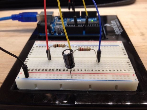
This tutorial provides a guide on how to set up an Arduino to measure the capacitance of a capacitor. This can be useful if the capacitor is unlabeled or if it is self-built.
Capacitance is an object’s ability to store an electric charge. Reasonably, this object is referred to as a capacitor. A capacitor that stores this charge in an electric field between two conductive plates is known as a parallel plate capacitor. The non-conductive material that is between these two plates is known as a dielectric. Dielectrics change the amount of charge a capacitor can hold and , in practice, what the particular capacitor would be used for (e.g. high frequency circuits, high voltage circuits, etc).
The equation for the capacitance of a parallel plate capacitor is:
C = (εA) / d
where ε is the permittivity of free space or dielectric, A is the surface area of overlap between the plates, and d is the distance between the plates.
An RC (Resistor-Capacitor) circuit has a property known as a “RC Time Constant” or T (Tau). The equation for which is given below:
T = RC
Tau can be simplified from a more complicated equation (shown in images above) to represent the time it takes a capacitor to be charged, through a resistor, to reach 63.2% of its total voltage. This can also be measured by the time it takes the capacitor to reach 36.8% of its total voltage upon discharging.
The Arduino will be programmed to time how long it takes for a capacitor to reach 63.2% of its total charge. It will then use the equation for Tau to calculate the capacitance since the value of the resistor is already known.
For more detail: Measure Capacitance with Arduino

