Summary of Linear Bench Power Supply
This article describes a DIY linear bench power supply designed for educational purposes, featuring adjustable 0-30V and 0-2A outputs with a fixed 5V rail. It avoids integrated regulators, using op-amps for feedback control alongside an Arduino-driven LCD display to monitor setpoints and measurements. The design utilizes a Darlington pass transistor, a common emitter signal transistor, potentiometers for settings, and specific voltage/current sensing circuits mapped to the 5V reference range.
Parts used in the Linear Bench Power Supply:
- Linear bench power supply circuit
- Op-amps (for voltage and current feedback)
- NPN Darlington transistor (main pass transistor)
- Small signal NPN transistor (common emitter configuration)
- Arduino microcontroller
- 20x4 character LCD display
- Potentiometers (voltage and current setting pots)
- 6:1 voltage divider
- 100mOhm resistor (current sensing)
- Mains rectification circuitry
- Transformer tap select
- 7805 5V regulator
DETAILED DESCRIPTION
This project is a simple linear bench power supply with adjustable voltage and current. It is meant to be a learning experience, putting ideas of circuit design, feedback, stability into practice building a complete practical power supply. I have intentionally avoided using a 3 terminal regulator or purpose built chip and instead implemented the feedback for voltage and current using a couple of opamps. The idea is for this to be a practical final product while giving pactice implementing some basic circuits.
Specs:
- 0-30V
- 0-2A
- separate fixed 5V output
- Display of setpoint and measured current and voltage
Beyond this, everything is kept as simple as possible with no additional features to compliacate the design. The display is a 20×4 character LCD controlled by an Arduino which reads the currents and voltages. The voltage and current are set by 2 pots on the front panel. There is no data logging or serial comms, although this could be added later if desired with an update to the arduino firmware.
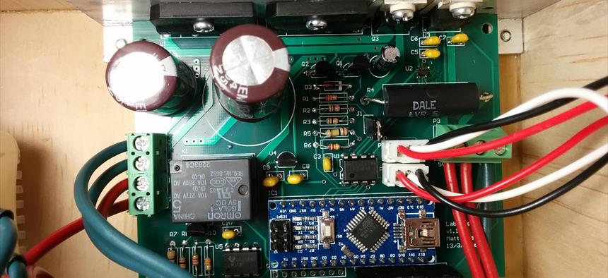
The design is fairly simple and uses a single npn darlington transistor as the main pass transistor in a common collector configuration. This provides current gain but no voltage gain, which is provided by a small signal npn transistor in a common emitter configuration. The current and voltage feedback loops are controlled by two opamps which compare the measured output values with setpoints generated by two potentiates on the front panel which are driven by a 5V reference.The output voltage is sampled via a 6:1 votlage divider (converts the 0-30V output to a 0-5V signal) and the current is sampled by measuring the voltage drop over a 100mOhm resistor in series with the output. Everything is mapped down to the 0-5V range so that they can be directly measured with an arduino using the 5V rail as the reference voltage.There is additional circuitry for the mains rectification, the transformer tap select and a 7805 5V regulator which provides the reference voltage, powers some of the chips and is routed to the front panel to provide a fixed 5V output.
For more detail: Linear Bench Power Supply
- What is the primary purpose of this project?
The project serves as a learning experience to practice circuit design, feedback, and stability by building a complete practical power supply. - How are voltage and current controlled in this design?
Voltage and current are controlled by two op-amps that compare measured output values with setpoints generated by two potentiometers on the front panel. - Does the design use a 3-terminal regulator or purpose-built chip?
No, the designer intentionally avoided using a 3-terminal regulator or purpose-built chip to implement feedback using op-amps. - What components are used to sample the output voltage and current?
The output voltage is sampled via a 6:1 voltage divider, and the current is sampled by measuring the voltage drop over a 100mOhm resistor. - Can data logging or serial communication be added later?
Yes, data logging or serial comms could be added later if desired with an update to the Arduino firmware. - What is the role of the 7805 5V regulator in this circuit?
The 7805 regulator provides the reference voltage, powers some chips, and routes a fixed 5V output to the front panel. - How does the system map signals for the Arduino?
Everything is mapped down to the 0-5V range so they can be directly measured with an Arduino using the 5V rail as the reference voltage.