Summary of LED DISPLAY SPEED METER CIRCUIT WITH AT89C51
This article describes a Speed Meter Circuit using an AT89C51 microcontroller. It features a sensor, power supply (12V DC), and a 7-segment display driven by hexadecimal conversion via a time code converter. The system regulates voltage to 5V for the microcontroller using a 7805 regulator and uses an op-amp with a comparator to process sensor signals, limiting input to 5.1V logic levels.
Parts used in the LED Display Speed Meter Circuit:
- DC 12V Supply
- Sensor
- AT89C51 Microcontroller
- 7-segment display technology
- Time code converter
- 7805 Voltage Regulator
- Op-Amp
- Comparator
- Potentiometer
- Zener Diode 5.1V
Speed Meter Circuit consists of four parts. These Supply solid floor Sensor sensor, microcontroller and microcontroller solid hexadecimal numbers we obtained from the 7-segment display technology with time code converter solid. Program Keil µVision3 AT89C51 microcontroller. Supply DC 12V… Electronics Projects, LED Display Speed Meter Circuit with AT89C51 “8051 example, avr project, keil example, microcontroller projects,
Speed Meter Circuit consists of four parts. These Supply solid floor Sensor sensor, microcontroller and microcontroller solid hexadecimal numbers we obtained from the 7-segment display technology with time code converter solid. Program Keil µVision3 AT89C51 microcontroller.
Supply DC 12V working with solids. However, by 7805 we have achieved solid display technology and microcontroller is supplied with 5V regulated. 12V opam the feeds OPAMPs from sensors to information received by the comparator works as and with the potentiometer we determine the reference voltage sensors have achieved with voltage compare output 0-12’re getting 12V to microcontroller directly would not go zener 5.1V a fix and this information logic 5V and 0V used it as we are .
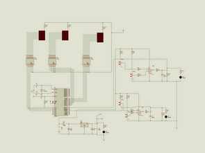
AT89C51 SPEED METER SCHEMATIC
AT89C51 LED Display Speed Meter Circuit keil source code and proteus isis simulation schematic files:
FILE DOWNLOAD LINK LIST (in TXT format): LINKS-3324.zip
Source: LED DISPLAY SPEED METER CIRCUIT WITH AT89C51
- What microcontroller is used in this circuit?
The circuit uses an AT89C51 microcontroller programmed with Keil µVision3. - How is the voltage regulated for the microcontroller?
A 7805 regulator converts the 12V supply to a stable 5V for the microcontroller and display. - Can I connect 12V directly to the microcontroller?
No, connecting 12V directly would damage it; a Zener diode of 5.1V is used to fix the logic level to 5V. - What component determines the reference voltage for the sensor?
A potentiometer is used alongside the comparator to determine the reference voltage from the sensors. - How does the op-amp function in this project?
The op-amp feeds information from the sensors to the comparator which works as a voltage comparison unit. - What software is used to program the microcontroller?
The AT89C51 microcontroller is programmed using Keil µVision3. - Where can I find the source code and simulation files?
The keil source code and proteus isis simulation schematic files are available in the LINKS-3324.zip download. - What is the output range of the voltage comparison?
The comparator outputs a voltage range between 0V and 12V before being limited by the Zener diode.