Summary of Large 7-Segment Clock,
The author rebuilds a faulty DIY 7-segment clock prototype caused by poor soldering and grounding on a homebrew PCB. The new design uses an Arduino with the Multiplex7Seg library, initially limited to four digits due to brightness constraints. To achieve a clean six-digit display without ghosting, the author switches to a custom multiplexing approach using NPN transistors for common-anode LEDs, planning to integrate a DS3231 RTC for accurate timekeeping and replace the messy wiring with a ribbon cable connection.
Parts used in the Large 7-Segment Clock:
- Arduino
- DS3231 RTC module
- 6x 7-segment LED displays (Common-Anode)
- Multiplex7Seg library
- 3904 NPN transistors
- Breadboard
- Ribbon cable
- MsTimer2 library (referenced as limiting factor)
Since it was one of the first things I ever built, I decided to put it in an enclosure of its own and consider it too as a finished product.
The problem was that the prototype never ran properly. It worked, just not as well as it should. Needless to say, I tried to fix it in the way of an Arduino upgrade. On paper everything should run perfectly, but in the real world, it just doesn’t. The clock bounces all over the place. It’s more of a random number generator than a clock. I really thought that moving away from the 60Hz line signal as a timebase to a solid 1Hz signal from a DS3231 RTC would solve all my problems. At the end of the day, it boils down to the fact that it’s all soldered together on a DIY homebrew PCB. The holes that I drilled are too big for the pins; resulting in some pretty shoddy-looking soldering. It’s a noisy circuit, and I’m sure there’s some grounding issues in there too.
 I put in a bunch of caps to help filter out the noise, but I think the board is just fundamentally flawed. You can polish a turd, but it’s still a turd.
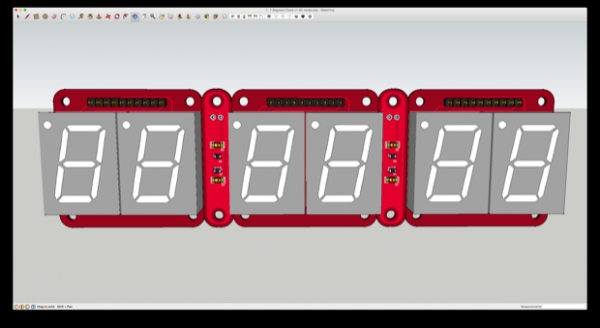
It’s just a shame to throw it in a closet and forget about it. The case came out so nice and it looks great in the living room. I’m going to gut it, and replace my old 7490 prototype board with something brand new. I’m going to keep it a 7-segment clock, so I’ll have to design a new PCB for the display.
I was thinking that I could just run the whole thing off the Bare Bones Arduino/DS3231 shield that’s running it now.
All I’d have to do is modify it so that I could connect the display to it. I’d have to string all 6 digits together and multiplex them. That’s 48 wires I’d have to solder onto the back of the display board.
That sounds like a real rat’s nest in the making. Not to mention, trying to unsolder the 48 wires that are on the back now and rewiring the whole thing not only seems like a daunting task, but a good way to damage some of the LED segments. When 7-segment LEDs only cost a buck or two, it’s better to just start off clean. Besides, I’d rather have a display PCB that I could just connect to a mainboard with a ribbon cable. Neat and tidy.
I thought about recycling my Mini 7-Segment LED Clock design and just breaking the digits out to a header that I could then connect to a display board with a ribbon cable, but again, it’ll probably be better (and cleaner) to just start from scratch.
The multiplexing on that clock is OK, but it’s not ideal. In order to make that clock as small as possible, I made it in a way that I wouldn’t need to use any transistors or LED driver chips. As a result, there’s sometimes a little ghosting on the digits and the first digit on the right is always a little brighter than the rest. If I’m going to do this, I’m going to do it right.
I got to work on prototyping something new. I decided to make use of the Multiplex7Seg library and drive the LEDs with transistors. Since I’m using common-anode LEDs, I can drive them with some 3904 NPN transistors. The following schematic shows these displays as having G1 and G2 connections. However, I’m using common-anode. I’ll pretend that those are anodes and not cathodes. If you were using common-cathode, you’d need to use 3906 PNP transistors and connect the emitter to Vcc.
#include <Multiplex7Seg.h>byte digitPins[] = { 9, 10};byte segmentPins[] = { 2, 3, 4, 5, 6, 7, 8};int num;void setup() { Multiplex7Seg::set(1, 4, digitPins, segmentPins); num = 0;}void loop() { num = num++; if (num == 99) { num = 0; } delay (200); Multiplex7Seg::loadValue(num); } |
The sketch has the digits count from 0-99, then start over. It runs great, and the LEDs look fantastic.
I added another 4 digits to my breadboard and attempted to modify my code to support the additional digits. It was then that I discovered that the Multiplex7Seg library is limited to 4 characters. That seemed to make sense considering the library is intended to be used with the commonly available 4×7 digit display variety; something I failed to realize when I downloaded it.
I was about to try and modify the library, but the notes within one of the files said not to bother; that “More than 4 digits is not practical since the brightness decreases with a faster refresh rate and the MsTimer2 library only goes to 1ms”. So that was basically the end of that.
I took a look at a few other examples online and figured out a better way to do it. It’s similar to the way that I multiplexed the digits on the Mini 7-Segment Clock, but a little more efficient. Not to mention, it looks even better. There’s no ghosting, and all the digits are of an equal brightness.
I’m just counting milliseconds here just to test the functionality, but soon I’ll add a DS3231 as a timebase.
For more detail: Large 7-Segment Clock,
- Why did the original clock prototype fail?
The prototype failed due to shoddy soldering from oversized drilled holes, noise issues, and grounding problems on a DIY homebrew PCB. - What component was intended to fix the timebase issues?
A DS3231 RTC was planned to provide a solid 1Hz signal instead of relying on the noisy 60Hz line signal. - Why was the Multiplex7Seg library abandoned for this project?
The library is limited to four characters because adding more digits causes brightness to decrease due to faster refresh rates and timer limitations. - How are the LEDs driven in the new design?
The design uses 3904 NPN transistors to drive common-anode LEDs for efficient multiplexing. - What problem does the new transistor-based design solve?
The new design eliminates ghosting and ensures all digits have equal brightness compared to the previous method. - How many wires would be required if rewiring the old display directly?
Connecting six digits together manually would require stringing 48 wires onto the back of the display board. - What is the preferred method for connecting the display to the mainboard?
The author prefers using a display PCB connected to a mainboard via a ribbon cable for a neat and tidy setup. - What type of transistors are needed for common-cathode LEDs?
If using common-cathode LEDs, you would need 3906 PNP transistors with the emitter connected to Vcc.