Summary of Interrupts in MSP430 – Writing GPIO Interrupt Program using Code Composer Studio
This article explains the necessity and types of interrupts in MSP430 microcontrollers, focusing on external GPIO interrupts to toggle LEDs via push buttons. It details register configurations (PxDIR, PxIN, PxOUT, etc.), circuit setup with resistors, and code implementation using Code Composer Studio. The tutorial covers interrupt handling, low power modes, and specific vector assignments for Port 1 and Port 2.
Parts used in the MSP430 Interrupt Project:
- MSP430G2 Launchpad
- Push-button switch
- Light Emitting Diodes (LEDs)
- Resistors (100ohm – 220ohm)
- Circuit board or breadboard
- Code Composer Studio (CCS) IDE
Consider a simple digital watch which is programmed to just show you time, now imagine you want to change its time zone. What would you do? You simply press a button that changes to the menu that enables you to change the time zone. Here, the system can’t predict your external interrupt to its time keeping processes and can’t ask you to wait since it is busy incrementing the seconds’ value on your watch. This is where the interrupts come handy.
Interrupts need not always be external; it can be internal too. Most times in an Embedded interrupt also facilitates communication between two peripherals of the CPU. Consider a pre-set timer is reset and an interrupt is triggered when the time reaches the value in the timer register. The interrupt handler can be used to initiate the other peripherals like DMA.
In this tutorial, we have used the external interrupts on MSP430 to toggle different LEDs. When an external interrupt is given by the change of state using a push-button, the control is transferred (pre-empted) to the ISR and it does the needful. To know the basics like CCS environment setup for the MSP430G2 launchpad, follow this link getting started with MSP430 using CCS because we will not get into details of that in this tutorial. Also check other MSP430 based tutorials using Energia IDE and CCS by following the link.
Why Do We Need Interrupt?
Interrupts are needed to save the polling overhead in an embedded system. They are called in when the tasks with higher priority are needed to be executed by pre-empting the current running task. It can also be used to wake the CPU from Low power modes too. When it is awakened by an external signal’s edge transition through a GPIO port, the ISR is executed and the CPU again returns back to the Low Power Mode.
Types of Interrupt in MSP430
The interrupts in MSP430 come under the following types-
- System Reset
- Non-Maskable Interrupt
- Maskable Interrupt
- Vectored and Non-Vectored Interrupts
System Reset:
It can occur due to supply voltage (Vcc) and due to a low signal in RST/NMI pin with Reset mode selected and can also occur due to reasons like watchdog timer overflow and security key violation.
Non-Maskable Interrupt:
These interrupts cannot be masked by the CPU instructions. Once the General Interrupt is enabled, the non-maskable interrupt cannot be diverted from processing. This is generated by sources like Oscillator faults and an edge manually given to the RST/NMI (in NMI mode).
Maskable Interrupt:
When an interrupt occurs and if it can be masked by a CPU instruction, then it is Maskable Interrupt. They need not be external always. They also depend on peripherals and their functions. The external port interrupts used here come under this category.
Vectored Interrupts and Non-Vectored Interrupts:
Vectored: In this case, devices that interrupt provide us with the source of the interrupt by passing the interrupt vector address. Here the address of the ISR is fixed and the control is transferred to that address and the ISR takes care of the rest.
Non-Vectored: Here all the interrupts have common ISR. When an interrupt occurs from a non-vectored source, the control is transferred to the common address, to which all the Non-vectored interrupts share.
Interrupt Program Control in MSP430
When the interrupt occurs, MCLK is turned ON and the CPU is called back from the OFF state. As the control of the program is transferred to the ISR address after the occurrence of the interrupt, the values in the program counter and the status register is moved on to the stack.
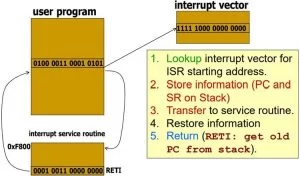
Consecutively, Status Register is cleared, thereby clearing the GIE and terminating the low power mode. Interrupt with the highest priority is selected and executed by placing the interrupt vector address in the program counter. Before we get to our MSP430 GPIO Interrupt Example Code, it is important to understand the working of Port registers involved in it.
Port Registers for GPIO Control on MSP430:
PxDIR: It is a port direction control register. It allows the programmer to specifically select its function by writing 0 or 1. If a pin is selected as 1, then it acts as an output. Consider port 1 to be an 8-bit port, and if the pins 2 and 3 are to be assigned as output ports, then the P1DIR register has to be set with the value 0x0C.
PxIN: It is a read only register and the current values in the port can be read using this register.
PxOUT: This particular register can be used to write values to the ports directly. This is possible only when the pullup/pulldown register is disabled.
PxREN: It is an 8-bit register used to enable or disable the pullup/pulldown register. When a pin is set as 1 in both the PxREN and PxOUT register, then the particular pin is pulled up.
| PxDIR | PxREN | PxOUT | I/O Config |
| 0 | 0 | X | Input with resistors disabled |
| 0 | 1 | 0 | Input with internal pulldown enabled |
| 0 | 1 | 1 | Input with Internal pullup enabled |
| 1 | X | X | Output – PxREN has no effect |
PxSEL and PxSEL2: As all the pins in MSP430 are multiplexed, the particular function has to be selected before using it. When both the PxSEL and PxSEL2 registers are set as 0 for a particular pin, then the general purpose I/O is selected. When the PxSEL is set as 1, the primary peripheral function is selected, and so on.
PxIE: It enables or disables interrupts for a particular pin in a port x.
PxIES: It selects the edge at which an interrupt is generated. For 0, a rising edge is selected and for 1, a falling edge is selected.
MSP430 Circuit to Test GPIO Interrupt
The MSP430 circuit used to test our MSP430 Interrupt Example code is shown below.
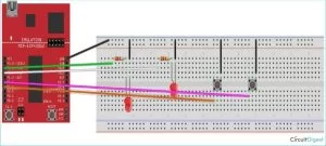
Ground of the board is used to ground both the LED and the button. The diagonally opposite sides of the push button are normally open terminals and get connected when the push button is pressed down. A resistor is connected before the LED to avoid the high current consumption by the LED. Usually, low resistors in the range of 100ohm – 220ohm are used.
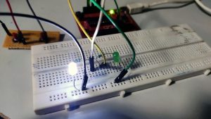
We use 3 different codes to get a better understanding of the port Interrupts. The first two codes use the same circuit as in the Circuit Diagram 1. Let us dive into the code. After the connections were made, my set-up looks like this.
Programming MSP430 for Interrupts
The complete MSP430 Interrupt Program can be found at the bottom of this page, the explanation of the code is as follows.
The below line stops the watchdog timer from operation. Watchdog timer usually performs two operations. One is preventing the controller from infinite loops by resetting the controller and the other is that it triggers periodic events using the inbuilt timer. When a microcontroller is reset (or powered up), it is in the timer mode and tends to reset the MCU after 32milliseconds. This line stops the controller from doing that.
WDTCTL = WDTPW + WDTHOLD;
Setting the P1DIR register to the value 0x07 sets the direction of pin0, pin1, and pin2 as output. Setting the P1OUT to 0x30 configures it an input with internal pullup resistors enabled on pin4 and pin5. Setting P1REN to 0x30 enables the internal pullup on these pins. P1IE enables interrupt, where P1IES selects the high to low transition as the interrupt edge on these pins.
P1DIR |= 0x07;
  P1OUT  = 0x30;
  P1REN |= 0x30;
  P1IE  |= 0x30;
  P1IES |= 0x30;
  P1IFG &= ~0x30;
Next line enables the low power mode and enables the GIE in the status register so that the interrupts can be received.
__bis_SR_register(LPM4bits+GIE)
The program counter is set with the address of the port 1 vector using the macro.
PORT1_VECTOR.
#pragma vector=PORT1_VECTOR
__interrupt void Port_1(void)
The below code toggles each of the LEDs connected to pin0, pin1, pin2 one by one.
if(count%3==0)
  {
  P1OUT ^= BIT1;
  P1IFG &= ~0x30;
  count++;
  }
  else if(count%3==1)
  {
      P1OUT ^= BIT1;
      P1IFG &= ~0x30;
      count++;
  }
  else
  {
      P1OUT ^= BIT2;
      P1IFG &= ~0x30;
      count++;
  }
Circuit Diagram 2:
Similarly, let’s try a different pin to understand the concept much better. So here the push button is connected to pin 2.0 instead of pin 1.5. the modified circuit is as follows. Again this circuit is used to test the MSP430 button interrupt program.
Source: Interrupts in MSP430 – Writing GPIO Interrupt Program using Code Composer Studio
- Why are interrupts needed in embedded systems?
Interrupts save polling overhead, allow higher priority tasks to preempt current ones, and wake the CPU from low power modes. - What are the main types of interrupts in MSP430?
The types include System Reset, Non-Maskable Interrupt, Maskable Interrupt, Vectored, and Non-Vectored Interrupts. - How does the PxREN register function?
PxREN enables or disables internal pullup/pulldown resistors; setting it to 1 along with PxOUT configures the pin pull state. - What is the purpose of the WDTCTL line in the code?
This line stops the watchdog timer from resetting the controller after 32 milliseconds upon power-up. - How do you configure a pin as an input with internal pullup enabled?
You must set the PxDIR bit to 0, PxREN bit to 1, and PxOUT bit to 1. - What happens when an interrupt occurs regarding the program counter?
The values in the program counter and status register are moved to the stack before control transfers to the ISR address. - Which edge transition triggers the interrupt in the provided example?
The example selects a high to low transition by setting the P1IES register bits. - What resistor range is recommended for the LED in the circuit?
A resistor between 100ohm and 220ohm is usually used to avoid high current consumption.