Summary of Simple GPIO Functions on Nuvoton N76E003 – LED Blinking and Controlling LED using a Push Button
Summary: This tutorial extends the N76E003 getting-started guide by showing how to use GPIO input and output: a push-button on P1.6 controls an external LED on P1.5 while the onboard Test LED on P1.4 blinks. It explains required hardware, pin selection, pin modes, code snippets (setup, infinite loop, software delay), and programming/verification with Keil and Nu-Link.
Parts used in the Simple GPIO Functions on Nuvoton N76E003 - LED Blinking and Controlling LED using a Push Button:
- N76E003 microcontroller based development board
- Nu-Link Programmer
- Push-button (tactile momentary switch)
- LED (any color) - external LED1
- Onboard Test LED (P1.4)
- 4.7k ohm resistor (pull-down)
- 100 ohm resistor (current limiting)
- Breadboard
- Hookup wires
In our previous tutorial, we used a basic LED blinking program as a getting started with N76E003 guide, we already learned how to configure the Keil IDE and set up the environment for programming the nuvoton microcontroller unit N76E003. It is the time to move a little bit further and use the basic GPIO interface for controlling additional hardware. If you are interested you can also check other microcontroller GPIO tutorials that are listed below-
- STM32 Nucleo64 with CubeMx and TrueSTUDIO – LED control
- STM8S with Cosmic C GPIO Control
- PIC with MPLABX LED Blink Tutorial
- MSP430 with Code Composer Studio – Simple LED Control
Since in our previous tutorial, we only used an LED to blink by using an IO pin as an output. In this tutorial, we will learn how to use another IO pin as an input and control an additional LED. Without wasting much time, let’s evaluate what kind of hardware setup we require.
Hardware Setup and Requirement
As a switch needs to be used as input, the first thing we require is a push button. We also require an additional LED to be controlled by that push button. Other than these two, we also require a resistor to limit the LED current and an additional resistor for the pull-down purposes across the pushbutton. This will be further demonstrated in the schematic section. The components we require –
- A push-button (any kind of momentary switch specifically – Tactile switch)
- Any color of the LED
- 4.7k resistor for pull-down purposes
- 100R resistor
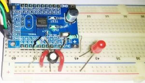
Not to mention, other than the above components, we need N76E003 microcontroller-based development board as well as the Nu-Link Programmer. Additionally, breadboard and hookup wires are also required for connecting all components as shown below.
N76E003 LED and Push Button Interface Circuit
As we can see in the below schematic, the Test LED that is inside the development board is connected on the port 1.4 and an additional LED is connected on the port 1.5. The resistor R3 is used to limit the LED current.
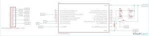
In pin 1.6, a push-button named SW is connected. Whenever the button is pressed, the pin will become high. Otherwise, it will become low by the 4.7K pull-down resistor R1. You can learn more about pull-up and pull-down resistors if you are new to this concept.
The pin is also a program related pin that is accessed by the programmer. It is used to send program data. However, we will see the reason behind selecting those pins as well as get fair information about the pin mapping of N76E003.
N76E003 Pin-Out Diagram
The pin diagram of N76E003 can be seen in the below image-
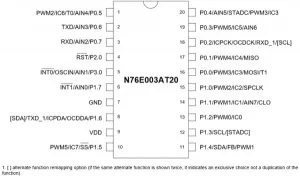

As we can see, each pin has multiple functions and can be used for different purposes. Let’s take an example. The pin 1.7 can be used as an interrupt, or analog input or as a general-purpose input-output operation. Thus, if any pin is used as I/O pins, then the respective functionality will not be available.
Due to this, the pin 1.5 which is used as an LED output pin, it’ll lose the PWM and other functionality. But that is not a problem as another functionality is not required for this project. The reason behind choosing pin 1.5 as output and pin 1.6 as input, because of the nearest availability of GND and VDD pins for easy connection.
However, in this microcontroller out of 20 pins, 18 pins can be used as a GPIO pin. The pin 2.0 is dedicatedly used for Reset input and it cannot be used as output. Other than this pin, all pins can be configured in the below-described mode.
As per the datasheet, PxM1.n, and PxM2.n are two registers that are used to determine the control operation of the I/O port. Now, coming to writing and reading a GPIO port is a completely different thing. Because writing to a port control register changes the latching state of the port, whereas reading the port gets the status of the logic state. But for reading a port, it must be set into an input mode.
Simple GPIO Control Program for N76E003
The complete program used in this tutorial can be found at the bottom of this page, the explanation of the code is as follows.
Setting the pin as input
Let’s start with the input first. As discussed just before, to read the status of a port, it needs to be set as input. Therefore, as we have selected P1.6 as our input switch pin, we have denoted it through the below line of code snippet.
#define SW P16
This same pin needs to be set as input. Thus, on the setup function, the pin is set as input using the below line.
void setup (void){
                P14_Quasi_Mode;
                P15_Quasi_Mode;
                P16_Input_Mode;
                }
This line P16_Input_Mode; is defined in the Function_define.h header file in the “BSP include library” that sets the pin bit as P1M1|=SET_BIT6; P1M2&=~SET_BIT6. The SET_BIT6 is also defined in the same header file as-
#define SET_BIT6 0x40
Setting the pins as output
Same as the input pin, the output pin that is used by the onboard Test LED and the external LED1 is also defined in the first section of the code with the respective PINs.
#define Test_LED P14
#define LED1 P15
Those pins are set as an output in the setup function using the below lines.
void setup (void){
                P14_Quasi_Mode; // Output
                P15_Quasi_Mode; // Output
                P16_Input_Mode;
                }
These lines are also defined in the Function_define.h header file where it sets the pin bit as P1M1&=~SET_BIT4; P1M2&=~SET_BIT4. The SET_BIT6 is also defined in the same header file as-
#define SET_BIT4 0x10
Infinite While loop
A Hardware, if connected with the power and working perfectly that should give output continuously, the application never stops. It does the same thing for infinite times. Here comes the function of an infinite while loop. The application inside the while loop runs infinitely.
  while(1){
             Test_LED = 0;
            sw_delay(150);
            Test_LED = 1;
            sw_delay(150);
             if(SW == 1){
                         LED1 = 0;
             }
             else {
                         LED1 = 1;
            }
}
}
The above while loop blinks the led as per the sw_delay value and also checks the status of the SW. If the switch is pressed, the P1.6 will be high, and thus when it is pressed, the read status will be 1. In this situation, for the time, the switch is pressed and the port P1.6 remains high, the LED1 will glow.
Programming N76E003 and Verifying Output
In our getting started with N76E003 tutorial, we learned how to program the N76E003 already, so we will just repeat the same steps here to program our board. The code compiled successfully and returned 0 warning and 0 Errors and flashed using the default flashing method by the Keil.
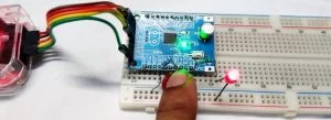
As you can see in the above image, our external LED turns on when I press the push button. The complete working of the project can be found in the video linked below. Hope you enjoyed the tutorial and learned something useful if you have any questions, leave them in the comment section below. You can also use our forums to ask other technical questions.
|
1
2
3
4
5
6
7
8
9
10
11
12
13
14
15
16
17
18
19
20
21
22
23
24
25
26
27
28
29
30
31
32
33
34
35
36
37
38
39
40
41
42
43
|
#include "N76E003.h"#include "SFR_Macro.h"#include "Function_define.h"#include "Common.h"#include "Delay.h"#define Test_LED P14#define LED1 P15#define SW P16void setup (void);void sw_delay (int ms);void main(void){ setup(); while(1){ <span style="white-space:pre"> </span> <span style="white-space:pre"> </span> Test_LED = 0;sw_delay(150);Test_LED = 1;sw_delay(150);if(SW == 1){LED1 = 0;} <span style="white-space:pre"> </span> else {LED1 = 1;}}}// Software-based delay. Time is not accurate.void sw_delay (int ms){int a, b;for (a=0; a<1296; a++){for (b=0; b<ms; b++);}}//This is the setup file before application runsvoid setup (void){P14_Quasi_Mode;P15_Quasi_Mode;P16_Input_Mode;} |
- What hardware is required to add a push-button controlled LED to the N76E003?
A push-button, an external LED, a 4.7k pull-down resistor, a 100R current-limiting resistor, an N76E003 development board, Nu-Link programmer, breadboard, and hookup wires. - Which pins are used for the onboard Test LED, external LED, and push-button in the tutorial?
Onboard Test LED is P1.4, external LED1 is P1.5, and the push-button SW is on P1.6. - How is the input pin configured in the code?
P1.6 is defined as SW and set to input mode using P16_Input_Mode in the setup function. - How are the LED output pins configured in the code?
P1.4 and P1.5 are defined as Test_LED and LED1 and set as outputs using P14_Quasi_Mode and P15_Quasi_Mode. - How does the program detect the button press and control LED1?
The main loop checks if SW equals 1 (button pressed) and sets LED1 low to turn it on; otherwise LED1 is set high to turn it off. - What does the infinite while loop do in the example program?
It continuously blinks the Test LED with sw_delay intervals and reads the switch state to update LED1 accordingly. - What header defines are used for pin bit settings?
Macros like SET_BIT6 and SET_BIT4 and mode macros in Function_define.h (e.g., P16_Input_Mode, P14_Quasi_Mode) are used. - Is the software delay accurate?
No, the sw_delay function is a software-based delay and the time is not accurate as noted in the code comments. - Why were P1.5 and P1.6 chosen for LED and switch?
They were chosen because of nearby availability of GND and VDD pins for easy connection and pin function trade-offs were acceptable for this project.