Summary of Interfacing PIC16F84 with DS3231 RTC
This article details a real-time clock and calendar project using a PIC16F84A microcontroller and DS3231 RTC module. Since the PIC lacks hardware I2C, software I2C is implemented via RA0 and RA1 pins. The system displays time on an LCD screen and allows users to adjust parameters like hours, minutes, date, month, and year using two push buttons. The code includes functions for BCD conversion and parameter editing with visual blinking feedback.
Parts used in the Real Time Clock and Calendar Project:
- PIC16F84A microcontroller
- 1602 LCD screen
- 8MHz crystal oscillator
- 2 x 22pF ceramic capacitor
- 10K ohm variable resistor
- 3 x 10K ohm resistor
- 2 x push button
- 5V supply source
- Breadboard
- Jumper wires
- DS3231 RTC module
- 2 x 4.7K ohm resistors (on DS3231 board)
- 0.1uF ceramic capacitor (on DS3231 board)
- 3V coin cell battery
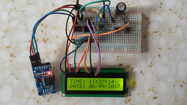
This post shows how to make a real time clock and calendar using PIC16F84 and DS3231 RTC.
The DS3231 uses I2C protocol to interface with the master device which is in this example the PIC16F84A MCU. In this project software I2C is used because the PIC16F84A MCU has no hardware I2C module.
Hardware Required:
- PIC16F84A microcontroller
- 1602 LCD screen
- 8MHz crystal oscillator
- 2 x 22pF ceramic capacitor
- 10K ohm variable resistor
- 3 x 10K ohm resistor
- 2 x push button
- 5V supply source
- Breadboard
- Jumper wires
DS3231 board contains the following components:
- DS3231 RTC – datasheet
- 2 x 4.7K ohm resistors
- 0.1uF ceramic capacitor
- 3V coin cell battery
Interfacing PIC16F84 with DS3231 RTC circuit:
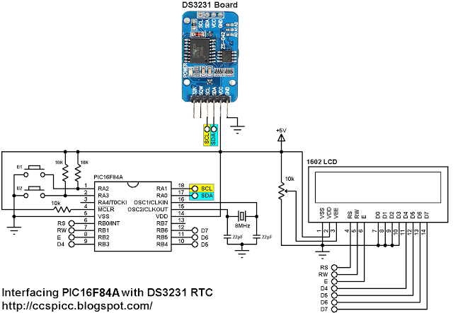
In the circuit there are 2 push buttons (B1 & B2) connected to pin RA2 and pin RA3, the two push buttons are used to set the time as well as the calendar parameters (minutes, hours, date, month and year). Button B1 selects the parameter and B2 increments the selected parameter.
Interfacing PIC16F84 with DS3231 RTC C code:
The C code below was tested with CCS PIC C compiler version 5.051.
I used the function below to initialize the software I2C where pin RA0 and pin RA1 are used for SDA and SCL lines respectively (PIC16F84A is used as master device):
#use I2C(MASTER, SDA=PIN_A0, SCL=PIN_A1, FAST=100000)
The DS3231 works with BCD format only and to convert the BCD to decimal and vise versa I used the 2 functions below. Before displaying (after reading from DS3231), the data have to be converted from BCD to decimal, and before writing to the DS3231 (after editing the parameters) the data have to be converted from decimal to BCD:
int8 bcd_to_decimal(number)
int8 decimal_to_bcd(number)
Each function returns the converted value of the variable number.
void DS3231_display() : displays time and calendar data, before displaying time and calendar data are converted from BCD format to decimal format using the function bcd_to_decimal(number) .
int8 edit(x, y, parameter) : I used this function to edit time calendar parameters (minutes, hours, date, month and year). I used a variable named i to distinguish between the parameters:
i = 0, 1 : time hours and minutes respectively
i = 2, 3, 4: calendar date, month and year respectively
After the edit of time and calendar, the data have to be converted back to BCD format using the function decimal_to_bcd(number) and written to the DS3231.
void blink() : this small function works as a delay except that it is interrupted by the buttons B1 (connected to RA2) and B2 (connected to RA3). When called and without pressing any button the total time is 10 x 25ms = 250ms. With this function we can see the blinking of the selected parameter with a frequency of 2Hz. So a delay of 250ms comes after the print of the selected parameter and after that delay a 2 spaces is printed which makes the parameter disappears from the LCD and another 250ms delay comes after the print of the 2 spaces.
for more detail: Interfacing PIC16F84 with DS3231 RTC
- How does the DS3231 interface with the PIC16F84A?
The DS3231 uses the I2C protocol to interface with the master device, which is the PIC16F84A MCU. - Why is software I2C used in this project?
Software I2C is used because the PIC16F84A MCU has no hardware I2C module. - Which pins are assigned for SDA and SCL lines?
Pin RA0 is used for SDA and pin RA1 is used for SCL lines. - What are the functions of push buttons B1 and B2?
Button B1 selects the parameter while B2 increments the selected parameter. - How is data handled between the DS3231 and the display?
Data must be converted from BCD to decimal before displaying and from decimal to BCD before writing to the DS3231. - What frequency is used for the blinking effect on the LCD?
The blinking frequency is 2Hz, achieved by a total delay of 250ms. - Can the PIC16F84A set the year parameter?
Yes, the project allows editing of the year along with minutes, hours, date, and month. - What compiler version was tested for the C code?
The C code was tested with CCS PIC C compiler version 5.051.