
Summary of Interfacing of PIC16F84A with DS1307 (RTC) code and Proteus simulation
This article provides C code and Proteus simulation for interfacing a DS1307 I2C real-time clock with a PIC16F84A using a software I2C implementation and displaying time on a 4-bit LCD. It explains pin assignments, pull-ups, initial time/date setup, and how the PIC acts as I2C master while DS1307 is the slave. The code was built with MPLAB and HI-TECH C and tested in Proteus.
Parts used in the DS1307 RTC with PIC16F84A Project:
- PIC16F84A microcontroller
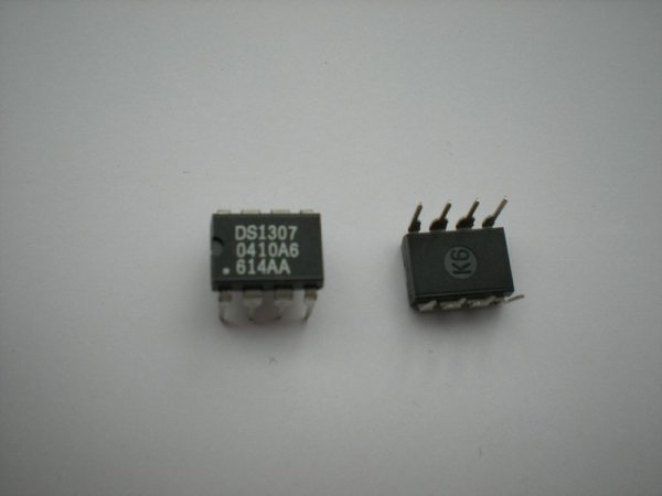
- DS1307 Real Time Clock (RTC) module
- 16x2 character LCD (interfaced in 4-bit mode)
- 10K pull-up resistors (for SDA and SCL lines)
- Connections for RA4 (SDA) pin
- Connections for RB0 (SCK/SCL) pin
- Proteus I2C Debugger Tool (for simulation/debugging)
- Power supply (Vcc and GND for devices)
This post provides the code for interfacing DS1307 RTC with PIC16F84A microcontroller. This DS1307 RTC has i2c based interface and PIC16F84A doesn’t have any built in i2c modules, so software i2c module is created in the code. This code is written in C language using MPLAB with HI-TECH C compiler. You can download this code from the ‘Downloads‘ section at the bottom of this page.
It is assumed that you know how to interface LCD with PIC16F84A microcontroller in 4bit mode. If you don’t then please read this page first, before proceeding with this article. It is also assumed that you know how to create software i2c module in PIC16F84A, if you don’t then please read this page first.
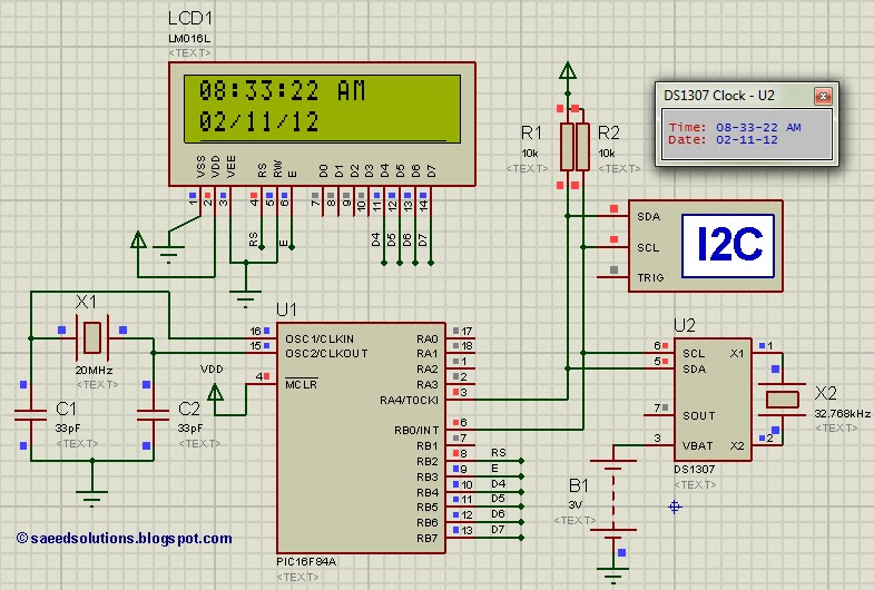
The result of simulating the code in Proteus is shown below.
In the above circuit[1], RA4 pin is being used as SDA pin and RB0 pin is the SCK pin. Both of these pins are pulled up using 10K resistors as required for i2c protocol. DS1307 RTC is the slave device, while PIC16F84A is configured to be the master. LCD is also attached with PIC16F84A, just to show the values received from the RTC, otherwise it is not required in this circuit. Proteus provides an ‘I2C Debugger Tool‘ which is attached on the SDA and SCK pins in the above circuit, this debugger shows all the activity on i2c bus[2]. It is attached in the circuit just for debugging purposes.
In the code, in the start a command is sent to DS1307 to set time to 8:32:59 AM and date to 2/11/12. After this, DS1307 starts to increment it’s time after every second. Then new time is read from DS1307 RTC after every second and displayed on the LCD. Figure 1 was taken when time was 8:33:22 AM, which is correctly displayed on the LCD.
Code
The code for the main function is shown below.
In the main function, firstly LCD is initialized using InitLCD() function. Then i2c pins are initialized using InitI2C() function. Then using Set_DS1307_RTC_Time(AM_Time, 8, 32, 59) function, a command is sent to DS1307 to set it’s time to 8:32:59 AM. After that, Set_DS1307_RTC_Date(2, 11, 12, Friday) command sets DS1307 date registers to 2/11/12 @ Friday date.
Downloads
DS1307 RTC interfacing with PIC16F84A code was compiled in MPLAB v8.85 with HI-TECH C v9.83 compiler and simulation was made in Proteus v7.10. To download code and Proteus simulation click here.
For more detail: Interfacing of PIC16F84A with DS1307 (RTC) code and Proteus simulation
- Can PIC16F84A interface with DS1307 which uses I2C?
Yes; the project uses a software I2C module because PIC16F84A has no hardware I2C. - Which pins are used for I2C in this setup?
RA4 is used as SDA and RB0 is used as SCK (SCL) in the described circuit. - Are pull-up resistors required on the I2C lines?
Yes; both SDA and SCL lines are pulled up with 10K resistors as required for I2C. - How is the initial time set on the DS1307 in the code?
The code sends a command using Set_DS1307_RTC_Time to set time to 8:32:59 AM and Set_DS1307_RTC_Date to set date to 2/11/12 Friday. - Does the PIC display the RTC data and how?
Yes; the PIC reads time every second from the DS1307 and displays it on an attached LCD. - Is an LCD required for the circuit to work?
No; the LCD is optional and used only to show values received from the RTC. - Which tools and compilers were used to develop and test the code?
The code was compiled with MPLAB v8.85 and HI-TECH C v9.83 and simulated in Proteus v7.10. - Does Proteus provide any tool to monitor I2C activity?
Yes; Proteus includes an I2C Debugger Tool which was attached to SDA and SCL for debugging.
