Summary of Interfacing DS1307 to PIC Microcontroller with C code and Circuit Diagram
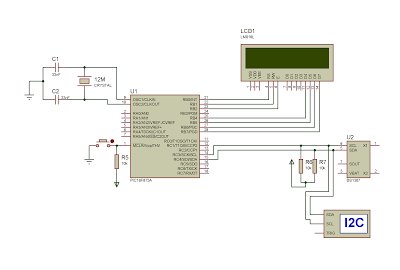
This tutorial details interfacing a DS1307 Real Time Clock with a PIC16F877 microcontroller using C code and the I2C protocol. The system reads time data from the RTC, converts BCD values to integers, and displays hours, minutes, seconds, date, month, year, and day on an LCD screen. The project utilizes the CCS compiler and is simulated in Proteus, where the PIC acts as the master device controlling communication via SDA and SCL pins with necessary pull-up resistors.
Parts used in the Interfacing DS1307 to PIC Microcontroller:
- DS1307 Real Time Clock (RTC)
- PIC16F877 Microcontroller
- Liquid Crystal Display (LCD)
- I2C Communication Lines (SDA and SCL)
- Pull-up Resistors
- Battery for Backup Power
- CCS Compiler
- Proteus Simulation Software
Interfacing DS1307 to PIC Microcontroller with C code and Circuit Diagram
This tutorial explains how to interface the DS1307 Real Time Clock (RTC) with a PIC16F877 microcontroller. The project is compiled using the CCS compiler and simulated in Proteus.
The DS1307 communicates with the PIC microcontroller through the I2C protocol, which is a two-wire, serial, synchronous, bi-directional communication method. Data is transferred via the SDA (Serial Data) and SCL (Serial Clock) pins. Pull-up resistors are required on these lines, and their values determine the communication speed. The master device controls the clock, and no data transfer occurs without it.
In this design, the PIC acts as the master, transmitting and receiving time data from the DS1307. The RTC values are read and displayed on an LCD.
 Embedded C Program for DS-1307 I2C Communication

Embedded C Program for DS-1307 I2C Communication
#include <16F877.h>
#include
#use delay(clock=4000000)
#define RTC_SDA PIN_C4
#define RTC_SCL PIN_C3
#use i2c(master, sda=RTC_SDA, scl=RTC_SCL)
void rtc_get_time();
int convert(int k);
int sec, min, hr, k[20], z, k1[20];
int day1, date, month, year;
void main() {
SETUP_ADC(ADC_OFF);
lcd_init();
while(1) {
rtc_get_time();
lcd_cmd(0x80);
sprintf(k, “%02d:%02d:%02d”, hr, min, sec);
lcd_array(k);
lcd_cmd(0xc0);
sprintf(k1, “%02d:%02d:%02d”, date, month, year);
lcd_array(k1);
lcd_cmd(0xc9);
switch(day1) {
case 1: lcd_str(“Sunday”); break;
case 2: lcd_str(“Monday”); break;
case 3: lcd_str(“Tuesday”); break;
case 4: lcd_str(“Wednesday”); break;
case 5: lcd_str(“Thursday”); break;
case 6: lcd_str(“Friday”); break;
case 7: lcd_str(“Saturday”); break;
}
}
}
void rtc_get_time() {
i2c_start();
i2c_write(0xD0);
i2c_write(0x00);
i2c_start();
i2c_write(0xD1);
sec = i2c_read();
min = i2c_read();
hr = i2c_read();
day1 = i2c_read();
date = i2c_read();
month = i2c_read();
year = i2c_read(0);
i2c_stop();
sec = convert(sec);
min = convert(min);
hr = convert(hr);
day1 = convert(day1);
date = convert(date);
month = convert(month);
year = convert(year);
z = ‘a’;
if(hr > 12) {
hr = hr – 12;
z = ‘p’;
}
}
int convert(int k) {
int a0, a1, a;
a0 = (k & 0x0F);
a1 = k >> 4;
a = (a1 * 10) + a0;
return a;
}
Above shows a simple program to read the Time value from DS-1307 IC. RTC Ds-1307 consumes very low power(500nA), so it can be backup by a battery for power failure issues. For DS1307, the device address is D0. The data, for example seconds value, located in the zeroth register is taken and converted from BCD to integer, before displaying it on the LCD. We can also write the Time value to Ds1307 registers one by one.
For more detail: Interfacing DS1307 to PIC Microcontroller with C code and Circuit Diagram
- How does the DS1307 communicate with the PIC microcontroller?
The DS1307 communicates through the I2C protocol using two-wire serial synchronous bi-directional communication methods. - What are the specific pins used for data transfer in this design?
Data is transferred via the SDA (Serial Data) and SCL (Serial Clock) pins. - Which component acts as the master device in this circuit?
The PIC microcontroller acts as the master device that controls the clock and initiates data transfers. - Does the DS1307 require external power during a failure?
No, the DS1307 consumes very low power of 500nA and can be backed up by a battery for power failure issues. - What is the device address for the DS1307?
The device address for the DS1307 is D0. - Why is a conversion function needed in the C program?
The conversion function is required to change the data from BCD format to integer before displaying it on the LCD. - Can the time value be written to the DS1307 registers?
Yes, you can write the Time value to DS1307 registers one by one. - What software tools were used to compile and simulate this project?
The project was compiled using the CCS compiler and simulated in Proteus.