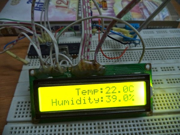
Summary of Interfacing DHT11 humidity and temperature sensor with PIC16F877A using pic microcontoller
This article details interfacing a DHT11 sensor with a PIC16F877A microcontroller using MikroC to measure humidity and temperature, displaying results on an LCD or error messages. It also briefly mentions future projects involving a DS1307 RTC, CD-ROM BLDC motors, and provides a standalone PIC16F877A LCD example code.
Parts used in the DHT11 Sensor Interface Project:
- DHT11 Sensor
- PIC16F877A Microcontroller
- LCD Module (16x2)
- MikroC Compiler
After interfacing the DHT11 with Arduino uno board at the following post:
ARDUINO Humidity & Temperature Measurement Using DHT11 Sensor
Now we are going to see how to interface this sensor with microchip pic16f877a.
There are some descriptions of how this sensor work in the above link
A brief description of the code:
The code is written using MikroC compiler.
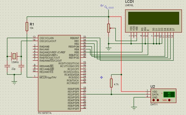
First we must send a start signal to the sensor, we do that by configuring the pic pin connected to the sensor as output, the mcu sends 0 for 18ms then sends 1 for 30us.
After sending start signal to the sensor, the sensor will send a response signal to the mcu. To detect this signal mcu pin must be configured as input.
When the sensor finishes the response signal, it begins sending humidity and temperature data serially.
If there is a problem with the sensor or there is no sensor connected to the circuit, the LCD displays “there is no response from the sensor”. And if there is a problem in the sensor which means the values are incorrect the LCD displays “Check sum error”.
If there is a problem with the sensor or there is no sensor connected to the circuit, the LCD displays “there is no response from the sensor”. And if there is a problem in the sensor which means the values are incorrect the LCD displays “Check sum error”.
// LCD module connections
 sbit LCD_RS at RB5_bit;
 sbit LCD_EN at RB4_bit;
 sbit LCD_D4 at RB3_bit;
 sbit LCD_D5 at RB2_bit;
 sbit LCD_D6 at RB1_bit;
 sbit LCD_D7 at RB0_bit;
 sbit LCD_RS_Direction at TRISB5_bit;
 sbit LCD_EN_Direction at TRISB4_bit;
 sbit LCD_D4_Direction at TRISB3_bit;
 sbit LCD_D5_Direction at TRISB2_bit;
 sbit LCD_D6_Direction at TRISB1_bit;
 sbit LCD_D7_Direction at TRISB0_bit;
 // End LCD module connections
 char *text,mytext[4];
 unsigned char  a = 0, b = 0,i = 0,t1 = 0,t2 = 0,
               rh1 = 0,rh2 = 0,sum = 0;
 void StartSignal(){
 TRISD.F2 = 0;    //Configure RD2 as output
 PORTD.F2 = 0;    //RD2 sends 0 to the sensor
 delay_ms(18);
 PORTD.F2 = 1;    //RD2 sends 1 to the sensor
 delay_us(30);
 TRISD.F2 = 1;    //Configure RD2 as input
  }
 void CheckResponse(){
 a = 0;
 delay_us(40);
 if (PORTD.F2 == 0){
 delay_us(80);
 if (PORTD.F2 == 1)   a = 1;   delay_us(40);}
 }
 void ReadData(){
 for(b=0;b<8;b++){
 while(!PORTD.F2); //Wait until PORTD.F2 goes HIGH
 delay_us(30);
 if(PORTD.F2 == 0)    i&=~(1<<(7-b));  //Clear bit (7-b)
 else{i|= (1<<(7-b));               //Set bit (7-b)
 while(PORTD.F2);}  //Wait until PORTD.F2 goes LOW
 }
 }
 void main() {
 TRISB = 0;        //Configure PORTB as output
 PORTB = 0;        //Initial value of PORTB
 Lcd_Init();
 while(1){
 Lcd_Cmd(_LCD_CURSOR_OFF);        // cursor off
 Lcd_Cmd(_LCD_CLEAR);             // clear LCD
  StartSignal();
  CheckResponse();
  if(a == 1){
  ReadData();
  rh1 =i;
  ReadData();
  rh2 =i;
  ReadData();
  t1 =i;
  ReadData();
  t2 =i;
  ReadData();
  sum = i;
  if(sum == rh1+rh2+t1+t2){
  text = "Temp:  .0C";
  Lcd_Out(1,6,text);
  text = "Humidity:  .0%";
  Lcd_Out(2,2,text);
  ByteToStr(t1,mytext);
  Lcd_Out(1,11,Ltrim(mytext));
  ByteToStr(rh1,mytext);
  Lcd_Out(2,11,Ltrim(mytext));}
  else{
  Lcd_Cmd(_LCD_CURSOR_OFF);        // cursor off
  Lcd_Cmd(_LCD_CLEAR);             // clear LCD
  text = "Check sum error";
  Lcd_Out(1,1,text);}
  }
  else {
  text="No response";
  Lcd_Out(1,3,text);
  text = "from the sensor";
  Lcd_Out(2,1,text);
  }
  delay_ms(2000);
  }
  }
Saturday, November 8, 2014
PIC16F877A LCD Example
This is just an example to show how to interface 16×2 lcd with pic16f877a. The lcd is going to display “PIC16F877A” in the the first line and “LCD Example” in the second line. The code is written using MikroC compiler.
// LCD module connections
sbit LCD_RS at RB5_bit;
sbit LCD_EN at RB4_bit;
sbit LCD_D4 at RB3_bit;
sbit LCD_D5 at RB2_bit;
sbit LCD_D6 at RB1_bit;
sbit LCD_D7 at RB0_bit;
sbit LCD_RS_Direction at TRISB5_bit;
sbit LCD_EN_Direction at TRISB4_bit;
sbit LCD_D4_Direction at TRISB3_bit;
sbit LCD_D5_Direction at TRISB2_bit;
sbit LCD_D6_Direction at TRISB1_bit;
sbit LCD_D7_Direction at TRISB0_bit;
// End LCD module connections
char *text;
void main() {
TRISB = 0;
PORTB = 0;
Lcd_Init();
Lcd_Cmd(_LCD_CURSOR_OFF);        // cursor off
Lcd_Cmd(_LCD_CLEAR);             // clear LCD
text = "PIC16F877A" ;
Lcd_Out(1,4,text);
text = "LCD Example";
Lcd_Out(2,4,text);
while(1);                     //infinite loop
}
 Tuesday, November 4, 2014
Real Time Clock
Now, I’m going to work with real time clocks, for that I will use the integrated circuit DS1307serial real time clock. I will use this ic with Arduino uno board and also I have to return to the pic microcontroller chip PIC16F877A. For the pic mcu I will use Microc and the full codes and schematics will be available on the next posts.
The DS1307 provides clock and calender. The clock shows seconds, minutes and hours and the calender shows day, month and year. The ds1307 uses I2C serial interface to transfer information with the microcontroller. More information in its datasheet.
The DS1307 provides clock and calender. The clock shows seconds, minutes and hours and the calender shows day, month and year. The ds1307 uses I2C serial interface to transfer information with the microcontroller. More information in its datasheet.
Cd-Rom 3 phase Sensored BLDC Motor Arduino Controller
BLDC (brushless dc) motors are three phase dc motors, unlike the simple dc motors the bldc motors are more difficult to control. These motors are used in many applications for examples rc airplans and rc cars.
In this post we will see how to control cd-rom sensored BLDC motor using Arduino uno board. But first there are some things we should know in order to control the motor in easy way.
The bldc motor that we are going to use is sensored via hall effect sensors (position sensors) attached with the motor(3 sensors). Each sensor outputs digital high for 180 electrical degrees and low for the other 180 electrical degrees.these sensors are used to tell us where is the position of the motor, then when we know the position of the motor we will energize just tow windings (of three). The below figure shows how sensors outputs and the corresponding voltage applied to the motor:
- How do you send a start signal to the DHT11 sensor?
The MCU configures the pin as output, sends 0 for 18ms, then sends 1 for 30us. - What happens if the sensor is not connected?
The LCD displays the message there is no response from the sensor. - How does the microcontroller detect the sensor's response?
The MCU pin must be configured as input after sending the start signal. - What indicates a checksum error on the display?
If values are incorrect, the LCD displays Check sum error. - Which compiler is used for the provided code?
The code is written using the MikroC compiler. - How many bits of data are read for each value like humidity?
The code reads 8 bits sequentially for each component (humidity high, humidity low, temp high, temp low). - What pins are used for the LCD module connections?
The LCD connects to PORTB pins RB0 through RB5. - Does the sensor send data serially?
Yes, the sensor begins sending humidity and temperature data serially after finishing the response signal.