Summary of How to work with External (Hardware) Interrupts of PIC Microcontroller (PIC18F4550)
Summary: This article explains hardware interrupts on the PIC18F4550, contrasting them with polling, listing internal and external interrupt sources, and describing the 10 control registers (RCON, INTCON/2/3, PIR1/2, PIE1/2, IPR1/2). It details INTCON registers and bits, edge selection in INTCON2, and INTCON3 priorities/flags. A worked example configures External Interrupt 0 (INT0) to toggle PORTD LEDs on a falling edge, showing required register settings and ISR code.
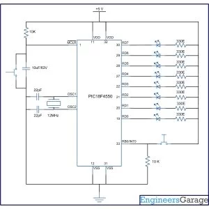
Parts used in the External Interrupt 0 Project:
- PIC18F4550 microcontroller
- LEDs (8 for PORTD display)
- Connections/wiring for LEDs to PORTD
- Power supply for PIC18F4550
- Programmer/debugger to load code (implied)
Interrupts are special events that require immediate attention. They cause the processor to cease the running task to serve a special task for which the interrupt event had occurred. After the special task is over, the processor resumes performing the original task.
A PIC microcontroller consists of both software and hardware generated interrupts. The hardware interrupts are produced by external hardware at certain pins of the microcontroller. The software interrupts, on the other hand, are generated by internal peripherals of the controller. This software interrupt helps the programmer to use more than one internal peripheral in single application and serve them individually when they respond.
· Reset, Brown-Out Reset, Watch-dog Reset, Power On Reset
· External Interrupt 0 (INT0)
· External Interrupt 1 (INT1)
· External Interrupt 2 (INT2)
· Timer 0 Interrupt
· Timer 1 Interrupt
· Timer 2 Interrupt
· Timer 3 Interrupt
· ADC Interrupt
· Analog Comparator Interrupt
· RB Port change Enable Interrupt
· Streaming Parallel Port Read/Write Interrupt
· EUSART Receive Interrupt
· EUSART Transmit Interrupt
· Master Synchronous Serial Port Interrupt
· CCP1 Interrupt (Capture, Compare, PWM)
· Oscillator Fail Interrupt
· USB Interrupt
· Data EEPROM/Flash Write Operation Interrupt
· Bus Collision Interrupt
· High/Low-Voltage Detect Interrupt
· CCP2 Interrupt
|
Bit 7
|
Bit 6
|
Bit 5
|
Bit 4
|
Bit 3
|
Bit 2
|
Bit 1
|
Bit 0
|
|
GIE/GIEH
|
PEIE/GIEL
|
TMR0IE
|
INT0IE
|
RBIE
|
TMR0IF
|
INT0IF
|
RBIF
|
Fig. 2: Bit Configuration of INTCON /Interrupt Control Register 1 for various hardware interrupt operation in PIC Microcontroller
|
Bit 7
|
Bit 6
|
Bit 5
|
Bit 4
|
Bit 3
|
Bit 2
|
Bit 1
|
Bit 0
|
|
RBPU
|
INTEDG0
|
INTEDG1
|
INTEDG2
|
—
|
TMR0IP
|
—
|
RBIP
|
|
Bit 7
|
Bit 6
|
Bit 5
|
Bit 4
|
Bit 3
|
Bit 2
|
Bit 1
|
Bit 0
|
|
INT2IP
|
INT1IP
|
—
|
INT2IE
|
INT1IE
|
—
|
INT2IF
|
INT1IF
|
Project Source Code
###
//Program to depict the working of External Interrupt0 of PIC18F4550
void main()
{
TRISD=0; // Configure PortD as output port
INTCON=0x10; // Enable INT0
INTCON2=0; // Set Falling Edge Trigger for INT0
INTCON.GIE=1; // Enable The Global Interrupt
while(1)
{
LATD=0x55; //Set some value at PortD
}
}
void interrupt() // Interrupt ISR
{
INTCON.INT0IF=0; // Clear the interrupt 0 flag
LATD=~LATD; // Invert (Toggle) the value at PortD
Delay_ms(1000); // Delay for 1 sec
}
###
Circuit Diagrams
Project Components
Project Video
Source: How to work with External (Hardware) Interrupts of PIC Microcontroller (PIC18F4550)
- What does an interrupt do in a PIC microcontroller?
An interrupt causes the processor to stop the current task and execute a special task, then resume the original task after the interrupt service is complete. - How many registers control interrupts in PIC18F4550?
A total of 10 registers control interrupt operation: RCON, INTCON, INTCON2, INTCON3, PIR1, PIR2, PIE1, PIE2, IPR1, and IPR2. - Which register bit enables External Interrupt 0 (INT0)?
INT0IE bit in the INTCON register enables or disables External Interrupt 0. - How do you set INT0 to trigger on a falling edge?
Set INTEDG0 bit in INTCON2 to 0 to select interrupt on falling edge. - What must be set to allow peripheral interrupts to be recognized?
PEIE/GIEL bit in INTCON must be set high, and the Global Interrupt GIE/GIEH bit must also be set high. - How is the global interrupt enabled?
By setting the GIE/GIEH bit in the INTCON register to 1. - What is the example project objective described in the article?
To configure External Interrupt 0 (INT0) to invert (toggle) the output on PORTD when the interrupt occurs, shown via 8 LEDs. - What steps are required in software to handle INT0 in the example?
Enable INT0IE, set INTEDG0=0 for falling edge, enable GIE, initialize PORTD, write ISR that clears INT0IF, toggles PORTD, and includes a delay. - Where does program execution jump when an interrupt occurs?
Execution transfers to a predefined Interrupt Vector Address where the ISR operations are defined.