Summary of How to Program a PIC Microcontroller to Build a Project
This article outlines the design and programming of a PIC microcontroller-based LED flashlight system. It highlights the advantages of LEDs over incandescent lights, detailing the use of the PIC16F877A microcontroller with a 4MHz crystal oscillator for precise timing. The project utilizes embedded C language within MPLAB and Proteus software to generate logic pulses that switch LEDs on and off. Key circuit elements include reset mechanisms using resistors and capacitors to ensure stable operation.
Parts used in the LED Flashlight System:
- Yellow LEDs
- Crystal
- Reset components (10k resistor and 10uf capacitor)
- PIC Microcontroller (PIC16F877A)
- Capacitors (20pf to 40pf range)
- Resistors
- MPLAB Compiler
- Proteus software
- Embedded C language
The recent trends in the advanced technology are helpful in developing most advanced electronic gadgets. Most of these electronic devices are developed using microcontrollers. The microcontroller is an electronic component, which is programmed to perform various control operations. There are various kinds of microcontrollers available, such as 8051, AVR, ARM, and PIC microcontrollers, etc., which are programmed by using the integrated development tools.
PIC Microcontroller
The PIC is a family of the microcontroller, which is manufactured by the different companies such as NXP, microchip, etc. The PIC stands for “peripheral interface controller”, which contains memories, timers/counters, serial communication, interrupts and ADC converters built into a single integrated chip.
 The PIC microcontrollers are found in most electronic devices such as alarm systems, traffic control systems and RFID based security systems, etc. The PIC microcontroller programming can be carried out to perform the huge range of tasks. Even though there are many types of PIC microcontrollers , the best and basic microcontroller is PIC16f877a.
PIC Microcontroller Programming Procedure
The PIC microcontrollers is programmed by the embedded C language or assembly language by using appropriate dedicated software. Before going to build a PIC microcontroller project, we must become aware of developing a basic microcontroller (like 8051) based project. Once you get the idea, this controller based project building becomes easy, so let us look at the basic steps to build a PIC microcontroller based project.
Before going to program the PIC microcontroller, first we have to select the right project that you are going program the microcontroller. As of now, consider the LEDs flash light system.
Theory:
The LEDs flashlight uses a set of light emitting diodes, and these are advanced to the traditional incandescent lights which consumes more energy and have very less life time. The LED lights on the other hand, consume less energy and have longer life.
Basic Idea of this Project Behind the Design:
The microcontroller generates the output logic pulses so that the LED light is switched ON and OFF at certain intervals. It is a 40 pin microcontroller. The Crystal interfaced to the input pins of the microcontroller provides accurate clock signals at the crystal frequency.
Circuit Designing
The PIC microcontroller transmit and receive the data with respect to clock pulses, the PIC microcontroller operates with 4MHz crystal frequency. Two capacitors are connected to the crystal oscillator with range of 20pf to 40pf which is used to stabilize the clock signals. At some times, the PIC microcontroller goes to block state or missing time calculation,at that time we need to reset the microcontroller. If a microcontroller is reset for 3sec time delay, 10k resistor and 10uf capacitor are connected to the respective pins.
Circuit Components
Hardware Components
- Yellow LEDs
- Crystal
- Reset
- PIC Microcontroller
- Capacitors
- Resistors
Software Components
- MPLAB Compiler
- Proteus software
- Embedded C language
Circuit Connections
The 5v DC supply is given to the 11 pin of the microcontroller which drives the circuit. The crystal is connected to the 13 and 14 pins of the microcontroller. The reset circuit is interfaced at 1 pins of the microcontroller. The Yellow LEDs is connected to the PORTB of the microcontroller.
 Circuit Diagram
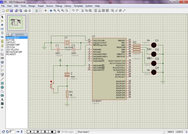
This circuit is designed with the help of Proteus software. The Proteus is a circuit designing software that contains a database of components, which we can use to build the circuit. Each and every component is available in the component library.
- Open the Proteus software. A window with a menu bar appears.
- Click the file menu.
- Select ‘new design’ from the drop-down menu.
- Click the library menu.
- Select ‘pick devices/symbol’ from the drop-down menu.
- Select the relevant comment by double clicking it, so that the electronic components list appear on the window.
- Add all the components and draw the circuit with the proper connections as shown above.
For more detail: How to Program a PIC Microcontroller to Build a Project
- What is the best basic microcontroller mentioned for this project?
The text identifies the PIC16F877a as the best and basic microcontroller. - How does the microcontroller control the LED lights?
The microcontroller generates output logic pulses to switch the LED light ON and OFF at certain intervals. - What frequency does the PIC microcontroller operate with in this design?
The PIC microcontroller operates with a 4MHz crystal frequency. - Can I program the PIC microcontroller using assembly language?
Yes, the PIC microcontrollers can be programmed by the embedded C language or assembly language. - Why are capacitors connected to the crystal oscillator?
Two capacitors connected to the crystal oscillator are used to stabilize the clock signals. - What happens if the microcontroller goes into a block state?
If the microcontroller goes to a block state or misses time calculation, it needs to be reset. - Which pins connect the crystal to the microcontroller?
The crystal is connected to the 13 and 14 pins of the microcontroller. - What voltage supply drives the circuit?
A 5v DC supply is given to the 11 pin of the microcontroller which drives the circuit. - What software is used to build the circuit diagram?
The circuit is designed with the help of Proteus software. - How long is the time delay required for resetting the microcontroller?
If a microcontroller is reset, a 3sec time delay is used.