Summary of How to Make a PIC Programmer – PicKit 2 ‘clone’
This article guides users in building a cost-effective DIY PIC programmer clone of the Microchip PicKit 2. It details sourcing components, designing and etching a custom PCB using Proteus software, soldering parts, and programming the core PIC18F2550 microcontroller with existing tools. The guide concludes with instructions on connecting the device to MPLAB IDEs for successfully programming other PIC chips.
Parts used in the PIC Programmer Clone:
- 2 x 100nF ceramic capacitor
- 2 x 15pF ceramic capacitor
- 2 x 47uF 16v electrolytic capacitor
- 1 x 10uF 16v electrolytic capacitor
- 2 x 1N4148 diode
- 1 x PIC18F2550
- 1 x 28 pin thin IC socket
- 1 x 680uH inductor
- 2 x 3mm LED (one green and one red)
- 3 x BC548 transistor
- 1 x BC557 transistor
- 1 x 20MHz oscillator crystal
- 3 x 33 ohm resistor
- 1 x 100 ohm resistor
- 2 x 330 ohm resistor
- 1 x 1k resistor
- 1 x 2k7 resistor
- 2 x 4k7 resistor
- 3 x 10k resistor
- 1 x 100k resistor
- 1 x 2-pin tactile switch
- 1 x pin strip (6 pins needed)
Hi! This is a short Instructable on making a PIC programmer which acts as a PicKit 2. I made this because it is way cheaper than buying an original PicKit and because Microchip, the manufacturers of PIC microcontrollers and the PicKit programmer, provides schematics and software, making it really easy for us to design our own programmers, definitely an advantage of using PICs.
Tools Needed:
- Soldering Iron and solder
- Wire Snips
- Needle Nose Pliers
- PCB etching tools and materials – Can be replaced with a breadboard but will take up more space
- Already working programmer (This is the downside, maybe you can borrow one)
- PC (for programming the PIC that goes into the PicKit)
Materials Needed:
- 2 x 100nF ceramic capacitor
- 2 x 15pF ceramic capacitor
- 2 x 47uF 16v electrolytic capacitor
- 1 x 10uF 16v electrolytic capacitor
- 2 x 1N4148 diode
- 1 x PIC18F2550
- 1 x 28 pin thin IC socket (for the PIC18F2550)
- 1 x 680uH inductor, resistor-like package
- 2 x 3mm LED (one green and one red)
- 3 x BC548 transistor
- 1 x BC557 transistor
- 1 x 20MHz oscilator crystal
- 3 x 33 ohm resistor
- 1 x 100 ohm resistor
- 2 x 330 ohm resistor
- 1 x 1k resistor
- 1 x 2k7 resistor
- 2 x 4k7 resistor
- 3 x 10k resistor
- 1 x 100k resistor
- 1 x 2-pin tactile switch (button)
- 1 x pin strip (only 6 needed)
Step 1: Schematics and PCB Design
For the schematics, I based my design on the one provided by Felixls in his page:
http://sergiols.blogspot.com.ar/2009/02/pickit-2-c…
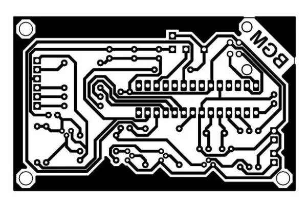
He also provided a PCB design, but I found that the traces were too thin to make at home, so I redesigned the PCB on Proteus.
Here are the files of the design and a pdf to print for making the PCB.
Attachments
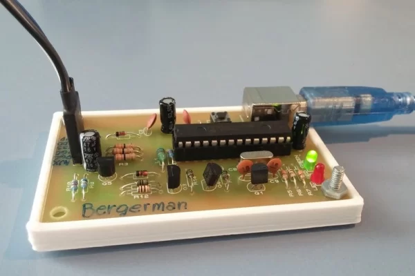
Step 2: Making the Board
If you want to learn how to make a PCB at home there are plenty of Instructables online where you can learn.
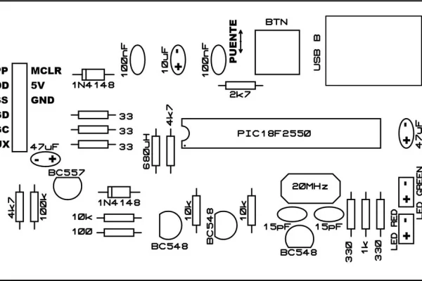
Once you have finished making the board you will need to solder the components, you can use these pictures to help.
Component list:
C1 100nf
C2 47uf 25v
C3 100nf
C4 47uf 25v
C5 10uf 50v
C8 15pf
C9 15pf
D1 1N4148
D2 1N4148
IC1 PIC18F2550
L1 680uH
LED RED LED 3MM
LED GREEN LED 3MM
Q1 BC548
Q2 20MHZ
Q3 BC548
Q4 BC548
Q5 BC557
R1 33
R2 33
R3 33
R4 4k7
R5 330
R6 1k
R7 330
R8 100k
R9 2k7
R10 4k7
R11 10k
R12 100
R13 10k
R14 10k
BTN tactile switch
SV3 6 pins
X3 USB B female
Step 3: Programming the Programmer
To program the PIC18F2550 to use in the programmer you will need a functioning PicKit. Once you get one or borrow one, you will need to install the PicKit 2 software: PicKit 2 v2.61
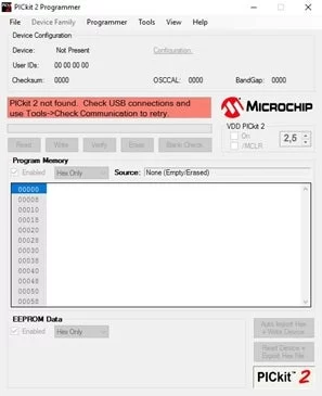
First open PicKit 2 and plug your functioning programmer. If it doesn’t say ‘PicKit connected’ in the message window, try clicking ‘Tools > Check communication’.
Then connect the PIC18F2550 to your functioning programmer using a breadboard and making the appropiate connections, like the image above shows.
If it isn’t detecting the PIC, showing ‘PIC Device Found’, then try clicking ‘Tools > Check communication’ a couple times. If it still doesn’t detect the PIC, check the connections.
To upload the program to the PIC go to ‘File > Import’, then ‘C:\Program Files (x86)\Microchip\PICkit 2 v2\PK2V023200.hex’ and click ‘Open’
Wait until it says ‘Hex file successfully imported’ and click ‘Write’ , the wait for it to say ‘Programming successful’
Step 4: Using the PicKit
First plug in our programmer and open PicKit 2. Wait for PicKit to detect the programmer, and if it doesn’t, click ‘Tools > Check Communication’.
Connect the PIC we want to program to our programmer. If you don’t know how you can search online for the pin distribution of the PIC and find the corresponding MCLR, VDD, VSS, PGD and PGC pins to connect to the programmer.
Wait for PicKit to detect the PIC showing ‘PIC Device Found’, if it doesn’t then try clicking ‘Tools > Check communication’ a couple times. If it still doesn’t detect the PIC, check the connections.
Open MPLAB, MPLAB X, or whichever IDE you are using and compile the program.
After compiling, go back to PicKit 2 and go to ‘File > Import Hex’. With MPLAB X you can find the hex file of your project in ‘Project_Directory > dist > default > production > Project_Name.production.hex’
Click ‘Write’ and wait for it to show ‘Programming Successful’
If you wish to modify your program you don’t need to import the hex file again, you should just compile it an click ‘Write’ in the PicKit software. Among the messages it displays it should read ‘Reloading hex file’ .
That’s it !
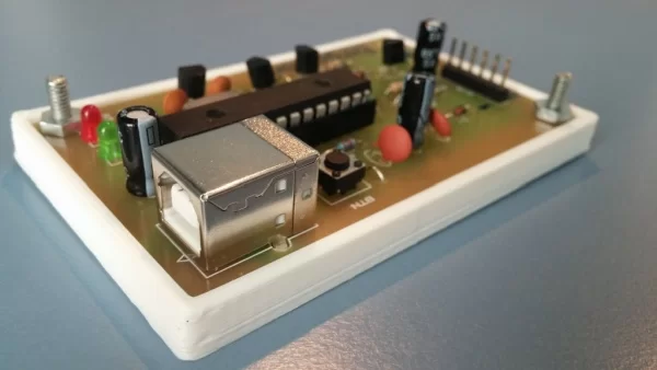
As a final step, you can design a simple rectangular case to 3d print just to protect the PicKit, you wouldn’t want it to break or short-circuit, I’ll leave it up to you.
Source: How to Make a PIC Programmer – PicKit 2 ‘clone’
- Why build this PIC programmer instead of buying an original?
It is significantly cheaper than purchasing an original PicKit while offering the same functionality. - What software is required to program the PIC18F2550 chip?
You need to install PicKit 2 v2.61 software to upload the necessary hex file. - Can I make the PCB at home if I do not have professional equipment?
Yes, you can use PCB etching tools or replace them with a breadboard, though the latter takes more space. - How do I verify communication between the PC and the programmer?
Click Tools > Check communication in the PicKit 2 software if the device is not detected. - Where is the hex file located when using MPLAB X?
The hex file is found in the Project_Directory > dist > default > production folder. - Do I need to re-import the hex file every time I modify my code?
No, you only need to compile the new program and click Write in the PicKit software. - What specific pins must be connected to program a target PIC?
You must connect MCLR, VDD, VSS, PGD, and PGC pins from the target PIC to the programmer. - Is it possible to protect the finished programmer from damage?
Yes, you can design and 3D print a simple rectangular case to prevent breakage or short circuits.