Summary of How to interface RFID with PIC18F4550 Microcontroller- (Part 15/25)
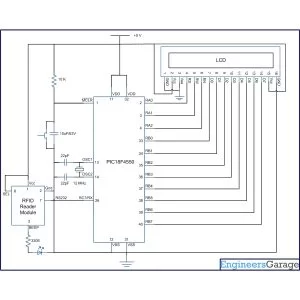
This article details interfacing an RFID reader module with a PIC18F4550 microcontroller to read 12-byte unique tag IDs and display them on an LCD. It eliminates external voltage converters by connecting the reader directly to the microcontroller, utilizing USART interrupts for data reception. The guide covers necessary register configurations (INTCON, PIR1, PIE1) and provides C source code for baud rate setup, interrupt handling, and LCD output.
Parts used in the RFID Interfacing Project:
- RFID Reader Module
- PIC18F4550 Microcontroller
- 16×2 LCD Display
- Resistors
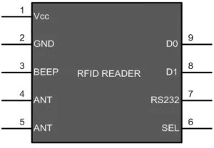
RFID (Radio Frequency Identification and Detection) is widely used everywhere from highly secured defense laboratories to school attendance system. By employing RFID, much secured entry systems can be developed without incurring huge costs. These are the reasons of excessive use of RFID technology. In this article, interfacing of an RFID reader module has been explained with PIC18F4550. The USART interrupt, an internal PIC interrupt, has also been explained. (For more details on USART, refer PIC EUSART)
|
Pin No.
|
Name
|
Description
|
|
1
|
Vcc
|
Supply Voltage; 5V
|
|
2
|
GND
|
Ground (0V)
|
|
3
|
BEEP
|
Beep or LED drive
|
|
4
|
ANT
|
No Use
|
|
5
|
ANT
|
No Use
|
|
6
|
SEL
|
High is RS232, Low is Weigand
|
|
7
|
RS232
|
TTL output data
|
|
8
|
D1
|
Weigand Data 1
|
|
9
|
D0
|
Weigand Data 0
|
|
Bit 7
|
Bit 6
|
Bit 5
|
Bit 4
|
Bit 3
|
Bit 2
|
Bit 1
|
Bit 0
|
|
GIE/GIEH
|
PEIE/GIEL
|
TMR0IE
|
INT0IE
|
RBIE
|
TMR0IF
|
INT0IF
|
RBIF
|
Fig. 4: Bit configuration of Interrupt Control Register in PIC18F4550
|
Bit 7
|
Bit 6
|
Bit 5
|
Bit 4
|
Bit 3
|
Bit 2
|
Bit 1
|
Bit 0
|
|
SPPIF
|
ADIF
|
RCIF
|
TXIF
|
SSPIF
|
CCP1IF
|
TMR2IF
|
TMR1IF
|
Fig. 5: Bit configuration of PIR1/ Peripheral Interrupt Request 1 in PIC18F4550
|
Bit 7
|
Bit 6
|
Bit 5
|
Bit 4
|
Bit 3
|
Bit 2
|
Bit 1
|
Bit 0
|
|
SPPIE
|
ADIE
|
RCIE
|
TXIE
|
SSPIE
|
CCP1IE
|
TMR2IE
|
TMR1IE
|
Fig. 6: Bit configuration of PIE1/Peripheral Interrupt Enable 1 PIC18F4550
Project Source Code
###
// Program to interface RFID module using EUSART in PIC18F4550
// Configuration bits
/* _CPUDIV_OSC1_PLL2_1L, // Divide clock by 2
_FOSC_HS_1H, // Select High Speed (HS) oscillator
_WDT_OFF_2H, // Watchdog Timer off
MCLRE_ON_3H // Master Clear on
*/
#define FREQ 12000000
#define baud 9600
#define spbrg_value (((FREQ/64)/baud)-1)
#define rs LATA.F0
#define rw LATA.F1
#define en LATA.F2
#define lcdport LATB
unsigned char rx_data();
void lcd_ini();
void lcdcmd(unsigned char);
void lcddata(unsigned char);
unsigned char data[]=”Unique ID No.”;
unsigned char card_id[12];
unsigned int i=0,pos;
void main()
{
TRISB=0; // Set Port B as output port
LATB=0;
TRISA=0;
LATA=0;
SPBRG=spbrg_value; // Fill SPBRG register to set the baud rate
RCSTA.SPEN=1; // To activate serial port (Tx and Rx pins)
RCSTA.CREN=1; // To enable continuous reception
PIE1.RCIE=1; // To enable the Reception (Rx) Interrupt
INTCON.GIE=1;
INTCON.PEIE=1;
lcd_ini(); // LCD initialization
while(data[i]!=”)
{
lcddata(data[i]); // To send characters one by one from ‘data’ array
i++;
}
while(1)
{
i=0;
while(i<12);
lcdcmd(0xC0);
i=0;
while(i<12)
{
lcddata(card_id[i]); // Print the 12 byte received data
i++;
}
}
}
void interrupt()
{
card_id[i]=RCREG; // Store the received data byte by byte
i++;
}
void lcd_ini()
{
lcdcmd(0x38); // Configure the LCD in 8-bit mode, 2 line and 5×7 font
lcdcmd(0x0C); // Display On and Cursor Off
lcdcmd(0x01); // Clear display screen
lcdcmd(0x06); // Increment cursor
lcdcmd(0x80); // Set cursor position to 1st line, 1st column
}
void lcdcmd(unsigned char cmdout)
{
lcdport=cmdout; //Send command to lcdport=PORTB
rs=0;
rw=0;
en=1;
Delay_ms(10);
en=0;
}
void lcddata(unsigned char dataout)
{
lcdport=dataout; //Send data to lcdport=PORTB
rs=1;
rw=0;
en=1;
Delay_ms(10);
en=0;
}
###
Circuit Diagrams
Project Components
Project Video
Source: How to interface RFID with PIC18F4550 Microcontroller- (Part 15/25)
- How can I interface an RFID reader without using MAX232?
You can connect the RFID reader directly to the microcontroller to eliminate the need for voltage level converters. - What is the function of the GIE/GIEH bit?
This global interrupt enable bit must be set high to enable all interrupts of the PIC18F4550. - Which register controls peripheral interrupts?
The INTCON register uses the PEIE/GIEL bit to enable or disable all peripheral interrupts. - How many bytes of data does an RFID tag contain?
An RFID tag contains 12 bytes of unique data that are transmitted when activated. - What baud rate is set for the PIC USART in this project?
The baud rate of the PIC's USART is set to 9600 bps. - Which bits activate the serial port in the RCSTA Register?
The SPEN and CREN bits must be set to 1 to activate the serial port and enable continuous reception. - What happens when the Reception Interrupt is generated?
The system stores the 12 byte data into an array when the Reception Interrupt is generated. - What is the purpose of the RCIF flag in the PIR1 register?
The RCIF flag is the reception interrupt flag which is set low when reception is complete.