Summary of How to interface keypad with PIC16F877
This tutorial shows how to interface a matrix keypad (4x4 or 4x3) with a PIC16F877 microcontroller using C (MPLAB + HI-TECH C). It uses PORTB for keypad rows and columns, and RD0, RD1, RD4–RD7 for an LCD to display the pressed key. The code scans columns/rows to detect key presses; simulation in Proteus demonstrates the LCD showing the pressed key. Downloads include the C code and Proteus simulation files.
Parts used in the Keypad with PIC16F877 Project:
- PIC16F877 microcontroller
- Matrix keypad (4x4 or 4x3)
- 16x2 LCD (interfaced via RD0, RD1, RD4-RD7)
- Proteus simulation software (for testing)
- MPLAB IDE (MPLAB v8.85 used)
- HI-TECH C compiler (v9.83 used)
- Connection wires / breadboard (or circuit in Proteus)
- Power supply for PIC and peripherals
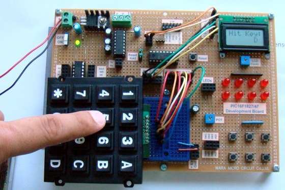
This PIC microcontroller tutorial provides a simple method to interface any keypad (e-g 4×4 or 4×3 etc) with PIC16F877 microcontroller.
This code is written in C language using MPLAB with HI-TECH C compiler. You can download this code from the ‘Downloads‘ section at the bottom of this page.
In this post, it is assumed that you know, how to interface LCD with PIC16F877 microcontroller, If you don’t then please read this page.
The circuit required to interface keypad with PIC16F877[1] is shown below.
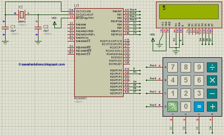
The result of simulating the code in Proteus is shown above in the figure. This code is written in such a way that when you press any key from the keypad, then the value of that key is displayed on the LCD. For example, in the above figure LCD screen is displaying ‘5’, because this picture was taken after pressing ‘5’ from the keypad.
In the above circuit, RD0, RD1 and RD4:7 pins are used to interface LCD with PIC16F877. LCD is used here just to show the pressed key value. 8 pins of PORTB are used to interface 4×4 keypad. 4 pins are used to attach columns and 4 pins are used to attach rows and scanning algorithm code is used to check for any pressed key.
Code
The main function code is shown below.
Downloads
Keypad interfacing code using PIC16F877 was compiled in MPLAB v8.85 with HI-TECH C v9.83 compiler and simulation was made in Proteus v7.10. To download code and Proteus simulation click here.
For more detail: How to interface keypad with PIC16F877
- How is the keypad connected to the PIC16F877?
Eight pins of PORTB are used: four for columns and four for rows, using a scanning algorithm to detect presses. - How is the pressed key shown to the user?
An LCD is connected (RD0, RD1, RD4-RD7) and displays the value of the pressed key. - Can both 4x4 and 4x3 keypads be used with this code?
Yes, the method supports any matrix keypad such as 4x4 or 4x3. - What compiler and IDE were used to develop the code?
The code was compiled with HI-TECH C v9.83 and developed in MPLAB v8.85. - Was the project tested in simulation?
Yes, the project was simulated in Proteus v7.10, showing the LCD displaying pressed keys. - Does this tutorial include the complete code and simulation files?
Yes, the code and Proteus simulation files are available for download from the Downloads section. - Do I need prior knowledge to follow this tutorial?
Yes, it is assumed you know how to interface an LCD with PIC16F877; the page links to LCD interfacing details if needed.