Microcontrollers are standalone chips since they have memory and processor embedded. The integrated memory of microcontrollers store embedded code and other temporary variables for the execution of program. CircuitsGallery published many microcontroller tutorials and PIC microcontroller projects. Sometimes we may use non-volatile memories (i2c devices) with microcontrollers in case of storing permanent data. In this article I am gonna explain how we interface an external memory i2c microchip with PIC microcontroller. For that I took Microchip’s 24LC64, which is a 64 Kbit Electrically Erasable PROM also called I2C. This i2c tutorial will definitely serve you while doing i2c projects.
 LCD module is used to display the data. Program progresses by writing data to the 24LC64 i2c memory chip then reading it and displaying on LCD screen.
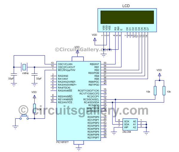
Schematics Diagram for Interfacing Microchip I2C EEPROM to PIC
Now let’s see the circuit diagram showing how to use i2c with PIC.
Components Required
- PIC 16F877 Microcontroller
- 24LC64 Memory chip (i2c datasheet)
- LCD Module
- Capacitors (33pF x 2)
- Crystal Oscillator 4MHz
- Resistor 10kΩ
How I2C Interface Works with PIC
- 16×2 LCD it is connected on PORTB of PIC which shows the read and write operations to the viewer.
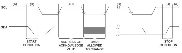
- Here two wire interface (with SCL and SDA pins) is used for the communication between Memory device and PIC Microcontroller also called “I square C (I2C)” or “inter integrated circuit”
- I2C has an advantage that can connect different device in same connection with the help of device address and start and stop signals.
- In such interfacing, PIC acts as a master and I2C memory servers as slave then master and slave communicate each other. (There are situation where we use i2c master, but not here)
- SCL (Serial Clock Line) is the clock line. It is used to synchronize all data transfers over the I2C bus and SDA (Serial DAta) is the data line.
- To start communication the channel should be ideal (means it not used by other devices and it is free), in ideal stat both the pins SDA and SCL by applying high signal.
For more detail: How to Interface I2C External EEPROM 24LC64 to PIC Microcontroller