Summary of How to Create a Garage Door Proximity Sensor
This article details the construction of a DIY garage proximity sensor using a PIC16F88 microcontroller and an HC-SR04 ultrasonic sensor. The project measures distance to a wall and displays it initially on an LCD before transitioning to a 4-LED proximity meter for efficiency. The guide covers circuit assembly, distance calculation logic using Timer1, code optimization by removing the LCD, implementing threshold-based LED control, adding measurement filtering via averaging, and optimizing power consumption through idle modes.
Parts used in the Garage Proximity Sensor:
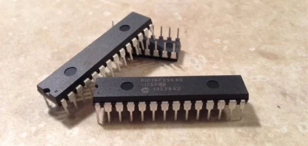
- PIC16F88 microcontroller
- PicKit 3 programmer
- Breadboard
- Power supply
- 16*2 characters LCD display (HD44780 controller)
- Brightness resistor
- Contrast potentiometer
- HC-SR04 ultrasonic sensor
- 4 LEDs (2 green, 1 orange, 1 red)
- 4 resistors (330 ohms)
If you don’t have a reverse backup radar system in your car, or if you park forward in your garage, you probably know this feeling of “am I too close, am I gonna hit the wall??”. There are a lot of ways to resolve this issue, but if you like tinkering with electronics and writing code, there’s only one way: create a home made electronic system.
I used a PIC16F microcontroller and a HC-SR04 ultrasonic sensor, but you can of course easily replicate this proximity sensor with any microcontroller you prefer.
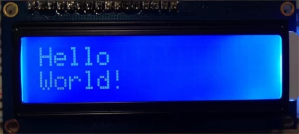
We’re first going to learn how to measure a distance with the ultrasonic sensor, and use a 2*16 LCD display to test the measuring. After we have this part down, we’ll implement an intuitive way to display the proximity to the wall, using 4 LEDs instead of the LCD display.
Step 1: List of Components
I won’t go in too much detail on the basic functioning of a PIC microcontroller, but you can find more information on those tutorials on how to set up the tools for programming PIC microcontrollers, and how to write your first PIC program.
Here is a list of the components we’ll need:
- A PIC16F88, or any microcontroller of your choice.
- A programmer for your microcontroller, if needed. For the PIC, I use a PicKit 3.
- A breadboard to build the circuit.
- A power supply of your choice. You can use a pre-made one from Amazon, or for more fun, you can build your own!
- A 16*2 characters LCD display, preferably based on a HD44780 controller. I use this one from Adafruit, which has the advantage of being sold with a pin header soldered. Also prepare a resistor for the brightness, and a potentiometer for the contrast.
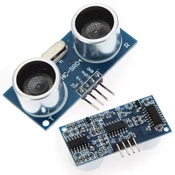
- A HC-SR04 ultrasonic sensor. Here is a $10 5-pack from Amazon.
- 4 LEDs: 2 green, 1 orange and 1 red.
- 4 resistors (330 ohms is perfect).
Step 2: Build the Circuit
Let’s build the circuit on the breadboard. Start by connecting the power supply to the power rails on the breadboard. Don’t power it until the full circuit is finished.
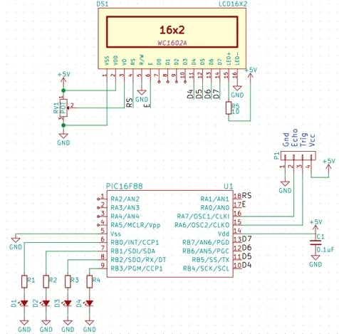
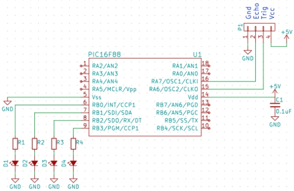
The ultrasonic sensor has 4 pins: Vcc, Trig, Echo and Gnd. To use it we’ll generate a high pulse on the trigger pin, and then the echo pin will generate a high signal which duration will tell us how long it took for the sound to go from the module to the obstacle and back. Connect Vcc to the +5V rail and Gnd to the ground. Connect Trig to the pin RA6 of the PIC (pin 15) and Echo to RA7 (pin 16). If you’re using a different microcontroller, Trig should be connected to any digital output, and Echo to any digital input.
For the LCD display, we’ll make the following connections, that you can also see on the schematic attached:
- Enable – RA0 (or any digital output)
- RS – RA1 (or any digital output)
- R/W – Ground (we only need to send data to the LCD display, and don’t need the read mode corresponding to R/W=1)
- Vss – Ground
- Vdd – +5V
- Vo – Connect to a potentiometer as shown on the schematic
- If your LCD display has a LED backlight, connect LED+ to +5V with a series resistor, and LED- to the ground.
- Data pins D4 to D7 – pins RB4 to RB7 (or any digital outputs). We’re going to use the 4-pin mode to control the LCD display, so we won’t use data pins D0 to D3. This allows us to use pins RB0 to RB3 of the PIC to control the LED proximity meter.
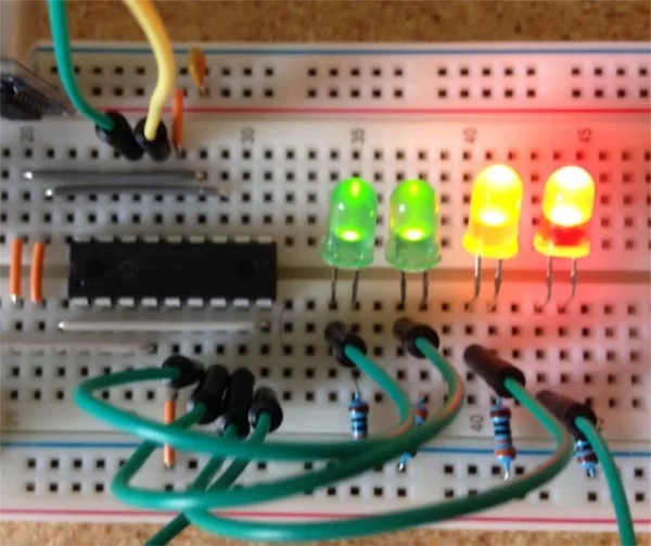
- Finally, connect the 2 green LEDs to RB0 and RB1, the orange one to RB2, and the red one to RB3. Don’t forget to put a 330 resistor in series with each LED.
Step 3: Logic for the Ultrasonic Sensor
Some math…
We need to do a bit of math to find out how to get the distance, when the sensor gives us a duration. As a reminder, the HC-SR04 will output a high signal on its Echo pin, and the duration of this signal will be the time it took for the signal to travel from the Trig pin, to the object and back. So we’ll need to divide this time by 2. We’ll see how to calculate a time with the microcontroller right down below. Let’s assume we have this time in seconds.
The speed of sound is v=340.3 m/s, which is v=34030 cm/s. Speed is calculated as v=d/t, with d being the distance, and t the time.
So the distance will be equal to d=v*t, which is d=(34030*t)/2. This gives us d=17015*t.
Logic for the HC-SR04 sensor
The first thing we need to do is get the duration during which the Echo pin produces a high signal. We are going to use the Timer1 on the PIC. Let’s configure it, using the T1CON register. First, set the clock source to be the internal clock. This means that the frequency of the clock used by the timer will be Fosc/4, in our case 2MHz, as our clock is set to 8MHz. We can disable the timer1 oscillator, as we are using the internal clock as a source. Turn the timer OFF initially, and set the prescaler to 2:1. This means that the frequency of the timer will be half of the clock source, which is 1MHz. That is, every 1us, the timer value will increase.
This gives us time_s = timer_time/1000000. And so d=17015*timer_time/1000000, which is d=0.017015*timer_time, or d=timer_time/58.77.
The code used to configure the timer is the following, in C language for XC8 compiler.
T1CONbits.TMR1CS = 0;   // Clock source is internal clock (Fosc/4)<br>T1CONbits.TMR1ON = 0;   // Timer off
T1CONbits.T1CKPS = 0b01;// Prescaler 2:1
T1CONbits.T1OSCEN = 0;  // Disable timer1 oscillator
Let’s put the code specific to the HC-SR04 into separate dist_measuer.c and .h files. Here is the content of the header file:
/*** CHANGE PINS BELOW ***/<br>#define HCSR04_TRIG         PORTAbits.RA6
#define HCSR04_TRIG_TRIS    TRISAbits.TRISA6
#define HCSR04_ECHO         PORTAbits.RA7
#define HCSR04_ECHO_TRIS    TRISAbits.TRISA7
/*** STOP CHANGES ***

/**
 * Initialize timer1 and pins of HC-SR04
 */
void HCInit();

/**
 * Calculate the time taken for signal to get to obstacle and come back
 * @return time, equal 2 times the distance to object
 */
uint16_t HCCalculateTime();

/**
 * Calculate the distance to object
 * @return distance in cm
 */
uint16_t HCCalculateDistance();
Here is the function HCCalculateTime(), which sends a signal on the trigger pin, and calculates the time during which echo stays high:
uint16_t HCCalculateTime() {<br>    uint16_t time = 0;

    // Reset timer
    TMR1L = 0;
    TMR1H = 0;

    // Trigger high/low
    HCSR04_TRIG = 1;
    __delay_us(20);
    HCSR04_TRIG = 0;

    // Wait for ECHO to be high
    while (!HCSR04_ECHO);
    T1CONbits.TMR1ON = 1;
    // Wait for ECHO to be low again
    while (HCSR04_ECHO);
    T1CONbits.TMR1ON = 0;

    // Read timer value
    time = (TMR1H << 8) | TMR1L;

    return time;
}
Finally, here is the function HCCalculateDistance(). It simply calls HCCalculateTime() and divides the time by 58.77:
uint16_t HCCalculateDistance() {<br>    uint16_t time = HCCalculateTime();
    uint16_t distance = time / 58.77;
    return distance;
}
You’ll notice that I used a type uint16_t for the time and the distance. This is because the timer saved its value in 2 8-bit registers, giving us a size of 16 bits. As for the distance, we could use a type uint8_t, but it would be limited to 255cm, which is 2.55m.
Step 4: LCD Library and Main Loop
I won’t detail here how to control a LCD display with a microcontroller, but you can find more details in this tutorial, and you can also find a PIC library for controlling HD44780-based LCD displays on this Github repository. Simply add the files LCD.c and LCD.h to your project, and change the name of the pins in LCD.h if you’re using different pins
As we’ve said before, we’re using the 4-bit mode to control the display. This means that anytime we want to send data on the data line, we’ll need to send the 4 MSB first, and then the 4 LSB.
If you want to test the system now, you only need to call the HCCalculateDistance, and then display the distance on the LCD display:
while(1) {
    // Get distance
    distance = HCCalculateDistance();
    // Print it on LCD display
    display_distance(distance);
    __delay_ms(1000);
}
The result is shown on the attached video. Now that we have a functional distance measuring logic, let’s see how to implement the proximity meter with the 4 LEDs!
Step 5: Getting Rid of the LCD Display
If you’re using a LCD display like I am, now is the time you can get rid of it. There are two main reasons why we want to remove the LCD display from the final version of this project. The first one is that printing text on the LCD display is using a lot of memory on the PIC for no reason. Our code related to the LCD, on a PIC16F88, takes around 20% of the program memory. To compare, we’ll see how much memory our program uses at the end of this tutorial. With the LCD related code, it takes 17% of the data memory and 39% of the program memory.
The second reason is simply that it is simply not needed in the final product. Being able to print text on a LCD display was helpful when writing the logic for distance measuring, but it will not be useful in the end.
On a side note, there were other options that we could have used to debug our program during development. I chose this method because it’s fun to display information visually on a display, but we could also have used the UART interface of the PIC to output text on a serial console on our computer.
This is an important thing to keep in mind when working with embedded systems. The resources of the systems we work with are often very limited, and while it’s convenient to have a way to display data, it’s rarely needed in the final product.
To get rid of the LCD display, simply remove it from the breadboard and remove all the connection that were related to it. You should be left with the attached circuit.
Step 6: Implement the Proximity Meter
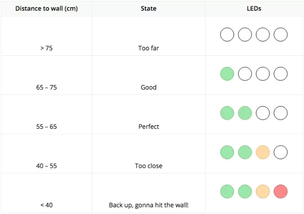
Determine the levels for the meter
The idea behind the proximity meter is simple. We have 4 LEDs that we’ll turn ON or OFF depending on the distance from the car to the wall. The colors of those LEDs will make it easy to quickly see how far we are from hitting the wall.
Knowing this, we can first determine the threshold distances we want to assign to each LED. For this, go in your garage with a tape measurer, and write down the limit distances for each of the following states. The distance I got for my garage are shown in the attached picture.
Let’s add those values to our program. We’ll define them as #define, which will make it easier to change them later if needed; we’ll just need to change those #define instead of changing the value everywhere it’s used in the code.
// Proximity levels (higher level = object is closer)
#define METER_LEVEL_1   75
#define METER_LEVEL_2   65
#define METER_LEVEL_3   55
#define METER_LEVEL_4   40
The logic to control the proximity meter
We’ll write a function update_proximity_meter() to take care of the meter. We’ll give it the distance in cm as a parameter, and it will turn each LED on or off depending on the distance.
void update_proximity_meter(uint16_t distance) {
    PORTBbits.RB3 = 0;
    PORTBbits.RB2 = 0;
    PORTBbits.RB1 = 0;
    PORTBbits.RB0 = 0;

    if (distance <= METER_LEVEL_4) {
        PORTBbits.RB3 = 1;
    }
    if (distance <= METER_LEVEL_3) {
        PORTBbits.RB2 = 1;
    }
    if (distance <= METER_LEVEL_2) {
        PORTBbits.RB1 = 1;
    }
    if (distance <= METER_LEVEL_1) {
        PORTBbits.RB0 = 1;
    }
}
Step 7: Logic for the Main Loop
We need to read the distance at regular intervals, and update the meter accordingly. But this is not very efficient; even when you’re not needing the system to tell you how close your car is, it will constantly be updating the meter.
There are many ways to make this more efficient. One of the best would be to use a PIR sensor to detect motion. When motion is detected, it would trigger an interrupt on the PIC and start the whole measuring / updating the meter process.
To keep it simple, and only use the components we’re already using, we’ll simply put the system to sleep after each reading. But we need to put the system in idle mode when the car is not in the garage, and when the car is parked but not moving anymore. In order to do this, we’ll use two different durations for the loop delay, and we’ll add a counter of identical distances:
// Delay between 2 distances measures (in ms)
#define DELAY_IDLE      5000    // When no object is close
#define DELAY_ACTIVE    750     // When an object is close

// If distance is the same for this many times, go to idle mode
#define THRESHOLD_COUNT_IDENTICAL   20
Here is the logic we’ll use:
- If the distance is greater than the largest threshold, use DELAY_IDLE
- If the distance has been the same for more than THRESHOLD_COUNT_IDENTICAL, use DELAY_IDLE
- Otherwise, we need to update the proximity meter more frequently, and we’ll use DELAY_ACTIVE
In the first two cases, we want the LEDs to be OFF. We’ll just call update_proximity_meter() with a distance greater than the largest threshold.
Here is the code for the main loop:
void main(void) {
    init();

    uint8_t count_identical = 0;
    uint16_t distance = 0;
    uint16_t prev_distance = 0;

    while(1) {
        // Get distance
        distance = HCCalculateDistance();

        // Update counter of identical
        if (distance != prev_distance) {
            count_identical = 0;
        } else if (count_identical <= THRESHOLD_COUNT_IDENTICAL) {
            count_identical++;
        }
        prev_distance = distance;

        // Update the meter
        if (distance >= METER_LEVEL_1 || count_identical >= THRESHOLD_COUNT_IDENTICAL) {
            update_proximity_meter(METER_LEVEL_1 + 1);  // All LEDs OFF
            __delay_ms(DELAY_IDLE);
        } else {
            update_proximity_meter(distance);
            __delay_ms(DELAY_ACTIVE);
        }
    }
    return;
}
As you can see, the code for the main function is pretty small. This is because we encapsulated as many code as we could. If we still had the LCD display in the project, we would just need to call the function display_distance() that we wrote in the first part of this tutorial, and this would just add one line to the main function. It’s very important to keep your code as modular as possible; it greatly improves the readability and maintainability of your program. In this example, anyone can quickly understand what the program does, even if the inner working of each function is not known.
Step 8: Filter the Measures
If you’ve experimented a bit with the distance measurer, and it’s easier if you still have the LCD display attached, you probably noticed that the distance value sometimes jumps for one single read, even though the object has barely moved. There’s an easy way to fix this issue and make the system more reliable. We’re going to filter the values, by simply averaging the distances over a given number of measures.
Let’s modify our dist_measure.c and .h files. The function HCInit() will now take an argument, which will be the number of measures. We’ll limit it to 5 samples per measure, so getting a distance doesn’t take too much time. We’ll use a static variable n_samples, that will be accessible by all functions in this file, but not by any other files.
Below is the modified code for the HCInit() function:
#define _XTAL_FREQ  8000000     // System clock frequency
static uint8_t n_samples;

/**
 * Initialize timer1 and pins of HC-SR04
 * @param number of samples for the filter
 */
void HCInit(uint8_t _n_samples) {
    [... PIC pins init code ...]

    // Save n_samples
    if (_n_samples > 5) {
        n_samples = 5;
    } else {
        n_samples = _n_samples;
    }
}
Now we just need to loop n_sample times in HCCalculateDistance(), and calculate the average of the n_samples values:
/**
 * Calculate the distance to object
 * @return distance in cm
 */
uint16_t HCCalculateDistance() {
    uint16_t time = 0;
    uint16_t distance = 0;

    uint8_t i = 0;
    for (i=0 ; i<n_samples ; i++) {
        time = HCCalculateTime();
        distance += time / 58.77;
        __delay_us(100);
    }

    distance /= n_samples;
    return distance;
}
And that’s it, now the distances returned by HCCalculateDistance() will be smoother, and this should get rid of the wrong values.
Step 9: Final Result
Full code
The full code for this project can be found on my Github page.
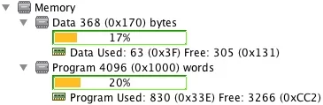
Memory consumption
As promised, let’s compare the memory consumption of this program, with what it was when we had the LCD display. It is much smaller than before, and this is only due to us removing the code related to the LCD display. The size of the program memory is half of what it used to be. And we also added some code for the averaging and for the delay logic!
Result
The result when moving the system closer/further away from a wall is shown on the attached video.
Improvements
There are many ways we could improve this device. I’ve listed some below, but feel free to experiment and implement your own ideas!
- Use a PIR motion sensor to trigger the system ON/OFF. It would be a much better idea than the logic we currently have with our delays, and would reduce the power consumption of the system.
- Add another level, when the car is much too close and about to hit the wall. You could blink the LEDs or emit a sound with a buzzer.
- Power the device with a battery, and get rid of the power cable.
Thanks for reading, and I hope this was helpful! Don’t forget to check The Embedded Lab for more tutorials!
Source: How to Create a Garage Door Proximity Sensor
- How do I calculate the distance using the HC-SR04 sensor?
Divide the time duration of the echo signal by 58.77 to get the distance in centimeters. - Can I use a different microcontroller for this project?
Yes, you can replicate the system with any microcontroller you prefer instead of the PIC16F88. - Why was the LCD display removed from the final version?
The LCD consumes too much memory for no reason in the final product and is not needed for the proximity meter. - What determines when each LED lights up?
Four defined threshold distances determine which LED turns on based on how close the car is to the wall. - How does the system save power when the car is parked?
The system enters idle mode after detecting the same distance value for a set number of consecutive readings. - How can I fix erratic distance readings?
You can filter the values by averaging multiple measurements over a given number of samples. - What is the best way to trigger the system only when needed?
Using a PIR motion sensor to detect motion and trigger an interrupt would be more efficient than constant polling. - How many bits are used to control the LCD display in this project?
The project uses 4-bit mode to control the LCD display to save digital output pins. - Where can I find the full code for this project?
The full code is available on the author's Github page mentioned in the article. - What happens if the distance is greater than the largest threshold?
All LEDs will turn off and the system will wait in idle mode between measurements.