Summary of How to configure EUSART in PIC18F4550 Microcontroller
Serial communication via PIC18F4550's EUSART is highlighted for long-distance transmission and error detection. The article details configuring registers like TXSTA, RCSTA, and BAUDCON to set asynchronous modes at 9600 baud. It explains full-duplex capabilities and provides C code to receive data from a PC and echo it back using HyperTerminal and MAX232 level conversion.
Parts used in the PIC18F4550 Serial Communication Project:
- PIC18F4550 Microcontroller
- MAX232 Level Converter
- PC with Windows HyperTerminal
- Circuit Board/Wiring
- 12MHz Crystal Oscillator
Both, Parallel and Serial modes of communication have certain advantages and disadvantages over one another. The serial communication is a preferred option due to its ability of long distance communication with error detection capability. The microcontrollers consist of an inbuilt hardware unit known as USART (Universal Synchronous Asynchronous Reception and Transmission) to facilitate serial transfer of data. For more details, refer to USART in AVR section.
Before starting USART, some general terms related to communication need to be understood. These terms are explained below.
|
Bit 7
|
Bit 6
|
Bit 5
|
Bit 4
|
Bit 3
|
Bit 2
|
Bit 1
|
Bit 0
|
|
CSRC
|
TX9
|
TXEN
|
SYNC
|
SENDB
|
BRGH
|
TRMT
|
TX9D
|
|
Bit 7
|
Bit 6
|
Bit 5
|
Bit 4
|
Bit 3
|
Bit 2
|
Bit 1
|
Bit 0
|
|
SPEN
|
RX9
|
SREN
|
CREN
|
ADDEN
|
FERR
|
OERR
|
RX9D
|
Fig. 5: Bit configuration of RCSTA /Receive Status and Control Register in EUSART of PIC Microcontroller
|
Bit 7
|
Bit 6
|
Bit 5
|
Bit 4
|
Bit 3
|
Bit 2
|
Bit 1
|
Bit 0
|
|
SPPIF
|
ADIF
|
RCIF
|
TXIF
|
SSPIF
|
CCP1IF
|
TMR2IF
|
TMR1IF
|
Fig. 6: Bit Configuration of PIR1 /Peripheral Interrupt Request Register of PIC’s EUSART
|
Bit 7
|
Bit 6
|
Bit 5
|
Bit 4
|
Bit 3
|
Bit 2
|
Bit 1
|
Bit 0
|
|
SPPIE
|
ADIE
|
RCIE
|
TXIE
|
SSPIE
|
CCP1IE
|
TMR2IE
|
TMR1IE
|
Fig. 7: Bit configuration of PIE1/ Peripheral Interrupt Enable Register 1of EUSART in PIC Microcontroller
|
Bit 7
|
Bit 6
|
Bit 5
|
Bit 4
|
Bit 3
|
Bit 2
|
Bit 1
|
Bit 0
|
|
ABDOVF
|
RCIDL
|
RXDTP
|
TXCKP
|
BRG16
|
—
|
WUE
|
ABDEN
|
|
Configuration Bits
|
BRG/EUSART Mode
|
Baud Rate Formula
|
||
|
SYNC
|
BRG16
|
BRGH
|
||
|
0
|
0
|
0
|
8-bit/Asynchronous
|
Fosc / [64 (n + 1)]
|
|
0
|
0
|
1
|
8-bit/Asynchronous
|
Fosc / [16 (n + 1)]
|
|
0
|
1
|
0
|
16-bit/Asynchronous
|
|
|
0
|
1
|
1
|
16-bit/Asynchronous
|
Fosc / [4 (n + 1)]
|
|
1
|
0
|
x
|
8-bit/Synchronous
|
|
|
1
|
1
|
x
|
16-bit/Synchronous
|
|
Project Source Code
###
// Program to depict the configuration of EUSART in PIC18F4550
// This code receives and then transmits the same data back to the PC .. // ..through PC’s Serial Port
// Configuration bits
/* _CPUDIV_OSC1_PLL2_1L, // Divide clock by 2
_FOSC_HS_1H, // Select High Speed (HS) oscillator
_WDT_OFF_2H, // Watchdog Timer off
MCLRE_ON_3H // Master Clear on
*/
void tx_data(unsigned char);
unsigned char rx_data(void);
unsigned char serial_data;
unsigned int i=0;
#define FREQ 12000000 // Frequency = 12MHz
#define baud 9600
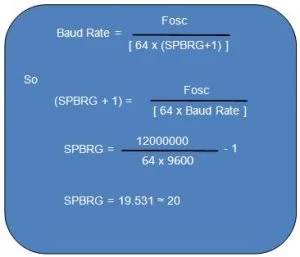
#define spbrg_value (((FREQ/64)/baud)-1) // Refer to the formula for Baud rate calculation in Description tab
void main()
{
SPBRG=spbrg_value; // Fill the SPBRG register to set the Baud Rate
RCSTA.SPEN=1; // To activate Serial port (TX and RX pins)
TXSTA.TXEN=1; // To enable transmission
RCSTA.CREN=1; // To enable continuous reception
while(1)
{
serial_data=rx_data(); // Receive data from PC
tx_data(serial_data); // Transmit the same data back to PC
}
}
void tx_data(unsigned char data1)
{
TXREG=data1; // Store data in Transmit register
while(PIR1.TXIF==0); // Wait until TXIF gets low
}
unsigned char rx_data(void)
{
while(PIR1.RCIF==0); // Wait until RCIF gets low
return RCREG; // Retrieve data from reception register
}
###
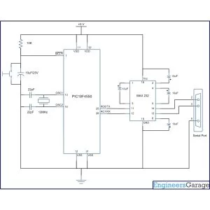
Circuit Diagrams
Project Components
Project Video
Source: How to configure EUSART in PIC18F4550 Microcontroller
- Why is serial communication preferred over parallel?
Serial communication is preferred due to its ability for long-distance communication and error detection capability. - What does the SYNC bit determine in the TXSTA register?
The SYNC bit selects the mode of communication where 1 indicates synchronous mode and 0 indicates asynchronous mode. - How does Automatic Baud-rate Detection work in EUSART?
EUSART sets the baud rate on its own during reception without needing manual setting at the controller side. - Which bits enable transmission and reception in the project?
The TXEN bit in TXSTA enables transmission and the CREN bit in RCSTA enables continuous reception. - What is the function of the SPBRG register?
The SPBRG register stores the lower byte value used to set the baud rate for serial communication. - How do you calculate the baud rate for 8-bit asynchronous mode?
The formula is Fosc divided by 64 times (n plus 1) when BRGH and BRG16 are set to zero. - What hardware converts signals between the microcontroller and PC?
A MAX232 level converter is used to interface the controller with the PC serial port. - When does the TXIF flag become high?
The TXIF flag becomes high when the TXREG register is empty indicating the transmitter is ready.