In this type of communication, a device can either behave as Transmitter or Receiver at an instant which means that a device can’t transmit data when it is receiving and vice versa.
PIC’s EUSART
PIC18F4550 has an inbuilt EUSART (Enhanced USART). Normally USART can be configured as asynchronous full-duplex communication or synchronous half-duplex communication. EUSART provides additional capabilities as compared to USART, like Automatic Baud-rate Detection. Automatic baud-rate detection means that during reception there is no need to set the baud rate at controller’s side, EUSART sets it on its own which is certainly an advantage over USART. Baud rate and its calculation have been explained later in this article.
Registers of EUSART:
To use the EUSART of PIC18f4550 microcontroller following registers need to be configured.
1. TXSTA (Transmit Status and Control Register)
Bit 7 | Bit 6 | Bit 5 | Bit 4 | Bit 3 | Bit 2 | Bit 1 | Bit 0 |
CSRC | TX9 | TXEN | SYNC | SENDB | BRGH | TRMT | TX9D |
Fig. 4: Bit configuration of TXSTA /Transmit Status and Control Register of EUSART in PIC Microcontroller
TRMT: This is a read only bit which shows the status of Shift register where data is stored.
1 = Transmit Shift Register Empty
0 = Transmit Shift Register Full
BRGH: This bit is configured to decide the speed of Asynchronous serial communication.
1 = High speed
0 = Low speed
SYNC: The mode of communication is selected by this bit.
1 = Synchronous mode
0 = Asynchronous mode
TXEN: This bit is set to high to enable the transmission.
TX9: This bit is set to high while sending 9-bit long data.
1 = Selects 9-bit transmission
0 = Selects 8-bit transmission
2. RCSTA (Receive Status and Control Register)
Bit 7 | Bit 6 | Bit 5 | Bit 4 | Bit 3 | Bit 2 | Bit 1 | Bit 0 |
SPEN | RX9 | SREN | CREN | ADDEN | FERR | OERR | RX9D |
Fig. 5: Bit configuration of RCSTA /Receive Status and Control Register in EUSART of PIC Microcontroller
CREN: This bit is set to high for continuous reception enable. To stop reception the bit is set to zero.
RX9: This bit is used when 9-bit long data is to be received.
1 = Selects 9-bit reception
0 = Selects 8-bit reception
SPEN: This bit is used to enable/disable the serial port. (Tx and Rx pins)
1 = Serial port enabled
0 = Serial port disabled
3. TXREG (EUSART Transmit Register)
The data to be transmitted is stored in TXREG register.
4. RCREG (EUSART Receive Register)
The data to be received is stored in RCREG register.
5. PIR1 (Peripheral Interrupt Request Register 1)
Bit 7 | Bit 6 | Bit 5 | Bit 4 | Bit 3 | Bit 2 | Bit 1 | Bit 0 |
SPPIF | ADIF | RCIF | TXIF | SSPIF | CCP1IF | TMR2IF | TMR1IF |
Fig. 6: Bit Configuration of PIR1 /Peripheral Interrupt Request Register of PIC’s EUSART
TXIF: This is transmitter interrupt flag bit. It becomes high when the TXREG register is empty.
RCIF: This is receiver interrupt flag bit. It becomes high when the RCREG register is full.
6. PIE1 (Peripheral Interrupt Enable Register 1)
Bit 7 | Bit 6 | Bit 5 | Bit 4 | Bit 3 | Bit 2 | Bit 1 | Bit 0 |
SPPIE | ADIE | RCIE | TXIE | SSPIE | CCP1IE | TMR2IE | TMR1IE |
Fig. 7: Bit configuration of PIE1/ Peripheral Interrupt Enable Register 1of EUSART in PIC Microcontroller
TXIE: This bit is set to high to enable the transmission interrupt.
RCIE: This bit is set to high to enable the reception interrupt.
7. BAUDCON (Baud Rate Control Register)
This register controls the baud rate and some special functionalities of serial communication like auto-baud rate detection, inversion of receiving data etc.
Bit 7 | Bit 6 | Bit 5 | Bit 4 | Bit 3 | Bit 2 | Bit 1 | Bit 0 |
ABDOVF | RCIDL | RXDTP | TXCKP | BRG16 | — | WUE | ABDEN |
Fig. 8: Bit Values and Modes of Baud Rate Control Register in PIC’s EUSART
BRG16: This bit is used to enable/disable 16-bit baud rate register.
1 = 16-bit Baud Rate Generator (BRG) – SPBRGH and SPBRG
0 = 8-bit Baud Rate Generator (BRG) – SPBRG only
This means if the BRG16 bit is set to high, the baud rate is decided by both SPBRGH and SPBRG registers; and if it is set to low, only SPBRG register will set the baud rate.
7. SPBRG & SPBRGH (EUSART Baud Rate Generator Register Low Byte and High Byte)
These registers are used to set baud rate for the serial communication. The two registers SPBRG & SPBRGH store lower byte and higher byte respectively.
Baud Rate:
The baud rate is the speed of data in serial communication. It is also known as bits per second (bps). PIC’s EUSART provides different communication modes like asynchronous, synchronous, high-speed and low speed etc. The baud rate for different EUSART modes can be decided by different formulae. The following table shows the baud-rate formulae for different EUSART communication modes.
Configuration Bits | BRG/EUSART Mode | Baud Rate Formula |
SYNC | BRG16 | BRGH |
0 | 0 | 0 | 8-bit/Asynchronous | Fosc / [64 (n + 1)] |
0 | 0 | 1 | 8-bit/Asynchronous | Fosc / [16 (n + 1)] |
0 | 1 | 0 | 16-bit/Asynchronous |
0 | 1 | 1 | 16-bit/Asynchronous | Fosc / [4 (n + 1)] |
1 | 0 | x | 8-bit/Synchronous |
1 | 1 | x | 16-bit/Synchronous |
Fig. 9: Baud rate formaula with bit values of EUSART in PIC
Here : x = Doesn’t matter
Fosc = Crystal frequency
n = Value of SPBRGH : SPBRG Register pair
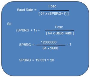
For example, if a Baud rate of 9600 is to be set for a 12MHz crystal and the mode is 8-bit, Asynchronous, then,
SYNC=0, BRG16=0 and BRGH=0 and the baud rate can be calculated, by using the following formula, as given below.

Objective: To first configure PIC18f4550 for asynchronous low-speed, 8-bit serial communication at 9600 baud rate. Next program the microcontroller to receive the serial data from a PC and transmit back the same data serially to the PC.
Window’s HyperTerminal has used to send and receive the data. To know more about HyperTerminal and working with it, refer to the last section in the Description of
Serial port interfacing with 8051.
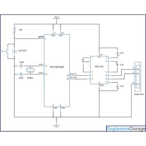
MAX232 has been used as level convertor between controller and PC. The connections are shown in circuit diagram tab.
Programming steps:
1. Configuration of EUSART-
· Set the baud rate by putting appropriate value in the SPBRG register.
· SPEN bit of the RCSTA register is set to high to activate serial port (Tx and Rx pins) of the controller.
· TXEN and CREN bits (in TXSTA and RCSTA registers) are set to high to activate serial transmission and serial reception respectively.
2. For Transmission-
· Store the data into TXREG register.
· Wait until transmission flag (TXIF) is equal to zero (PIR1 register).
3. For Reception-
· Wait until reception flag (RCIF) is equal to zero (PIR1 register).
· Store the value of RCREG register in some variable. This value is the received data.
Project Source Code
###
// Program to depict the configuration of EUSART in PIC18F4550
// This code receives and then transmits the same data back to the PC .. // ..through PC’s Serial Port
// Configuration bits
/* _CPUDIV_OSC1_PLL2_1L, // Divide clock by 2
_FOSC_HS_1H, // Select High Speed (HS) oscillator
_WDT_OFF_2H, // Watchdog Timer off
MCLRE_ON_3H // Master Clear on
*/
void tx_data(unsigned char);
unsigned char rx_data(void);
unsigned char serial_data;
unsigned int i=0;
#define FREQ 12000000 // Frequency = 12MHz
#define baud 9600
#define spbrg_value (((FREQ/64)/baud)-1) // Refer to the formula for Baud rate calculation in Description tab
void main()
{
SPBRG=spbrg_value; // Fill the SPBRG register to set the Baud Rate
RCSTA.SPEN=1; // To activate Serial port (TX and RX pins)
TXSTA.TXEN=1; // To enable transmission
RCSTA.CREN=1; // To enable continuous reception
while(1)
{
serial_data=rx_data(); // Receive data from PC
tx_data(serial_data); // Transmit the same data back to PC
}
}
void tx_data(unsigned char data1)
{
TXREG=data1; // Store data in Transmit register
while(PIR1.TXIF==0); // Wait until TXIF gets low
}
unsigned char rx_data(void)
{
while(PIR1.RCIF==0); // Wait until RCIF gets low
return RCREG; // Retrieve data from reception register
}
###
Circuit Diagrams

Project Components
Project Video