
Summary of Homemade temperature LED display for PC using PIC16F876
This project creates a custom water-cooling monitoring system using an LM50B sensor for 1°C accuracy, replacing inaccurate motherboard sensors. A PIC16F876 microcontroller processes four analog inputs to drive up to eight common-cathode LED displays, allowing real-time temperature tracking of the CPU, chipset, graphics card, and hard drives. The circuit features input protection resistors and utilizes a stable 2.56V reference voltage generated by either a precision regulator or an LM317 setup, powered directly from a hard drive connector.
Parts used in the Homemade Temperature LED Display:
- LM50B temperature sensor
- PIC16F876 microcontroller
- Common cathode LED displays (2 to 8 digits)
- N-FET transistors (e.g., IRF530) or NPN transistors
- 1k resistors for base inputs and sensor protection
- 2.56V reference voltage regulator (precision or LM317 configured)
- Hard drive power connector (5V supply)
Since I started my watercooling prejoect, I have been verry interested in how well it perform,
the only way is to measure all temperatures before and after,
The motherboard temperature sensors is useless unacurate, so I’m using LM50B
By using this LM50B sensor I get 1 C of real accuracy
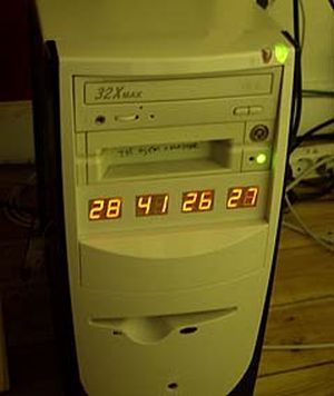
I use a PIC16F876 to drive a four two digits LED displays, the PIC16 has 4 analog inputs with 10 bits resolution,
now I can display 4 temperatures at the same time to monitor performance 🙂
I monitor CPU, Chipset, GFX card, Harddisks.
Here is the schematic good old handdrawn original..
Here is the schematic Re-Drawn Maybe you like this better 🙂 OK, comments for the circuit:
You can use any number of LED displays: 2, 4, 6, or all 8, depending on how many temperatures you want to display,
LED display type must me common cathode, FET can be any N-FET type you have, I have used IRF530 I had on stock,
NPN transistors can also be used if you dont have fets, then remember to mount a 1k resistor on each base inpus.
Each sensor input connector is protected using a 1k resistor, so you can connect sensors with power on,
nothing will burn if you connect it wrong.
Only calibration requred is the refference voltage, it need to be exactly 2.5600 volt, I have used a super stable regulator,
but an LM317 can also be used to make 2.56 volt with if that is what you have. DOWNLOAD The HEX file for the PIC16F876.
The 5 volt supply is taken from a free harddrive power connector, no need to regulate it, 4.8 to 5.2 will work fine.
This complete circuit with 8 all digits consume about 100mA. Good Luck.
For more detail: Homemade temperature LED display for PC using PIC16F876
- Why is the motherboard temperature sensor considered useless?
The article states that motherboard temperature sensors are inaccurate compared to the custom solution. - What level of accuracy does the LM50B sensor provide?
The LM50B sensor delivers 1 degree Celsius of real accuracy. - How many temperatures can be monitored simultaneously with this setup?
The system monitors four temperatures at the same time using four analog inputs on the PIC16F876. - Which type of LED display is required for this circuit?
The design requires common cathode LED displays. - Can I use NPN transistors instead of FETs?
Yes, NPN transistors can be used if you do not have FETs, provided you mount a 1k resistor on each base input. - How is the sensor input protected against incorrect connections?
Each sensor input connector is protected using a 1k resistor to prevent damage even if connected incorrectly while powered on. - What is the exact reference voltage required for calibration?
The reference voltage must be exactly 2.5600 volts for proper calibration. - Where does the 5 volt supply come from?
The 5 volt supply is taken from a free hard drive power connector without needing regulation.
