Summary of An LDmicro Tutorial
Summary: This tutorial shows building a simple PIC16F876-based ladder-logic program in LDmicro: one pushbutton cycles an LED through off, steady on, and blinking states. It covers hardware selection and schematic (pushbutton to Vdd with pull-down, ceramic resonator), creating an oscillator in ladder logic, using a circular counter for states, and mapping states to the LED output. It also explains entering the ladder diagram in LDmicro.
- PIC16F876 microcontroller (DIP)
- Three-terminal resonator (ceramic resonator with internal caps)
- Pushbutton
- Pull-down resistor for pushbutton
- LED
- Current-limiting resistor for LED
- Additional resistors as needed (e.g., for breadboard wiring)
- Solderless breadboard (or PCB for final build)
- Power supply (Vdd and ground)
In this tutorial, I will show you how to write a very simple program. I am assuming that you have written ladder logic before, and that you have some basic familiarity with microcontrollers, but that you have never used LDmicro. If you don’t know very much about ladder logic or PLCs, then the plcs.net tutorial might be helpful to you.
Our device will have one pushbutton, and one LED. At startup, the LED will be off. When you press the pushbutton once, the LED will turn steady on. The second time you press the pushbutton, the LED will start blinking. The third time that you press the button, the LED will turn off again. On subsequent presses, the cycle will repeat.
Microcontroller Selection and Schematic
We will be using a PIC16F876, which is easily available from Digikey or other online distributors. It comes in a number of different packages; I chose a DIP.
Note that as of Nov 2009, the PIC16F876 is no longer recommended for new design. This means that it will probably get discontinued at some point in the next few years. You may prefer to instead use a PIC16F886, which is pin-compatible. If you do, then make sure to specify the correct part when you compile, since the ‘F886 is not code-compatible.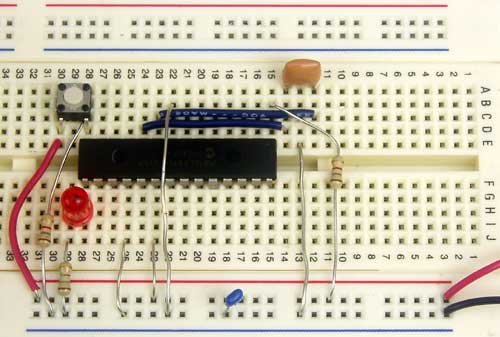
This is our schematic:
The microcontroller (IC1) is part number PIC16F876-20I/SP-ND at Digikey. Almost any three-terminal resonator (U1) will do; you might try a 535-9356-ND or an X909-ND.
The only thing that might confuse you is that the pushbutton goes to Vdd, and there is a pull-down. You might be more used to seeing a pushbutton to ground with a pull-up. For TTL, this mattered. For modern CMOS it does not, and I find this `active HIGH’ arrangement less confusing than the traditional `active LOW’ circuit.
Also, I chose to use a ceramic resonator with internal capacitors, U1, instead of a crystal and two ~20 pF caps. A crystal would work just as well and it would be more accurate, but it would be a little bit more expensive, and you would need more parts.
You could build this circuit in many different ways. I built it on a solderless breadboard, and it ended up looking like this:
(The resistor values pictured are not quite the same as the schematic; none of them are critical.)
Ladder Diagram for the Program
First, we are going to need an oscillator to generate the `blinking’ signal for the LED. There is a standard way to do this in ladder logic:
This will flash at 1/((250+250) ms), or 2 Hz, or twice per second. The duty cycle will be 50%—250 ms on, then 250 ms off. This circuit can make any kind of oscillator, with whatever period or duty cycle you require, so it is a good one to remember.
Also notice that we have chosen to use an internal relay (`Rfoo’) instead of one attached to an I/O pin (`Yfoo’ or `Xfoo’). This makes sense, because there is no particular reason to bring that signal out to a pin. LDmicro will automatically assign memory for the internal relay.
Our program will have three states: off, steady on, and blinking. The program should change its state on each rising edge of the signal from the pushbutton. This is a good application for a circular counter. We will say that `state 0′ is `off,’ `state 1′ is `steady on,’ and `state 2′ is `blinking.’ The counter counts 0, 1, 2, 0, 1, 2, …, so if we just let the rung-in condition of the counter be the pushbutton input, then everything will work like we want:
Now the only thing left is to use the program state to set the state of the LED. We can do it like this:
It should be easy to convince yourself that this does what we want. If the program is in state 1, then the `Cstate == 1′ instruction energizes `Yled’, as desired. In state 2, the `Cstate == 2′ instruction energizes `Yled’, but only when `Rosc’ is also true. Since `Rosc’ is oscillating, that means that the LED will blink, as desired. Finally, in state 0, neither of the equals instructions will be true, so there is no way that `Yled’ could ever turn on.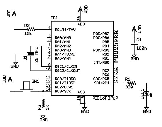
Entering the Ladder Diagram
Now that we have our circuit, we can draw it in LDmicro. When you start LDmicro, you will see a single empty rung:
We want to enter the first rung from the listing above. We will start with the coil, so choose Instruction -> Insert Coil. This will create a coil named `Ynew.’ This is what we want, except that the name is wrong, and it should be negated. Double-click the coil; this will bring up a dialog where we can fill that in:
Now we can insert the rest of that rung in the same way. Click on the left edge of the coil, so that the cursor is vertical, and to the left of the coil. Now choose Instruction -> Insert TON (Delayed Turn On). Once again double-click the timer to rename it and set the period. Add the TOF timer and the contacts in the same way.
Now we want to enter the second rung, so choose Edit -> Insert Rung After. Then click on the second rung to move the cursor there:
For more detatl: An LDmicro Tutorial
- What microcontroller is used in the project?
The project uses a PIC16F876 microcontroller (DIP package in the tutorial). - Can I use a different PIC than PIC16F876?
You can use a PIC16F886 which is pin-compatible, but you must specify the correct part when compiling because it is not code-compatible. - How is the pushbutton wired?
The pushbutton goes to Vdd and uses a pull-down resistor so the input is active HIGH when pressed. - Why use a ceramic resonator instead of a crystal?
A ceramic resonator with internal capacitors is cheaper and requires fewer parts than a crystal and two ~20 pF caps, though a crystal would be more accurate. - How is the blinking oscillator implemented in ladder logic?
The oscillator uses a pair of timers (TON and TOF) in a standard ladder arrangement to produce a 250 ms on / 250 ms off oscillation (2 Hz, 50% duty cycle). - How are the three LED states implemented?
A circular counter cycles through states 0 (off), 1 (steady on), and 2 (blinking) on each rising edge of the pushbutton input; state comparisons control the LED. - How does the LED blink only in state 2?
In state 2, the Cstate == 2 instruction energizes the LED output only when the internal relay Rosc (the oscillator) is true, causing blinking. - Do I need to expose the internal relay to an I/O pin?
No; the tutorial uses an internal relay Rosc instead of assigning it to an I/O pin, and LDmicro will allocate memory for it automatically.