Summary of Heart Beat Monitoring using PIC Microcontroller and Pulse Sensor
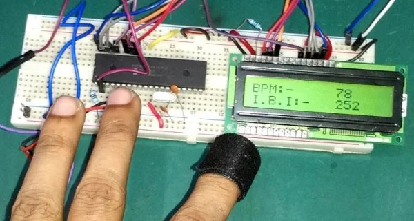
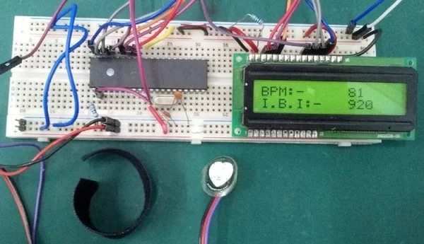
This project demonstrates a heart rate monitoring system using a PIC16F877A microcontroller and a SEN-11574 pulse sensor. The system reads analog signals from the sensor via ADC, calculates Beats Per Minute (BPM) and Inter-Beat Interval (IBI), and displays the results on a 16x2 LCD. A 20MHz crystal provides timing, while a timer interrupt facilitates data acquisition every 2 milliseconds.
Parts used in the Heart Beat Monitoring System:
- PIC16F877A microcontroller
- 20 Mhz Crystal
- 33pF capacitor 2 pcs
- 4.7k resistor 1 pcs
- 16x2 Character LCD
- 10K pot for contrast control of the LCD
- SEN-11574 Pulse sensor
- Velcro strap
- 5V Power adapter
- Breadboard and hookup wires
Heart Beat rate is most important parameter in monitoring any person’s health. In the modern era of wearable devices, there are lot of devices which can measure heartbeat, blood pressure, footsteps, calories burnt and lot of other things. These devices has pulse sensor inside them to sense the pulse rate. Today, we will also use a pulse sensor with PIC Microcontroller to count heart beat per minute and the Inter-Beat Interval, these values will be further displayed on 16×2 character LCD. We will use PIC16F877A PIC microcontroller in this project. We already interfaced pulse sensor with Arduino for Patient Monitoring System.
Required Components
- PIC16F877A microcontroller
- 20 Mhz Crystal
- 33pF capacitor 2 pcs
- 4.7k resistor 1 pcs
- 16×2 Character LCD
- 10K pot for contrast control of the LCD
- SEN-11574 Pulse sensor
- Velcro strap
- 5V Power adapter
- Breadboard and hookup wires
Pulse Sensor SEN-11574
To measure the heartbeat we need a pulse sensor. Here we have selected SEN-11574 pulse sensor which is easily available on online or offline stores. We used this sensor as there are sample codes provided from the manufacturer, but that is an Arduino code. We converted that code for our PIC microcontroller.
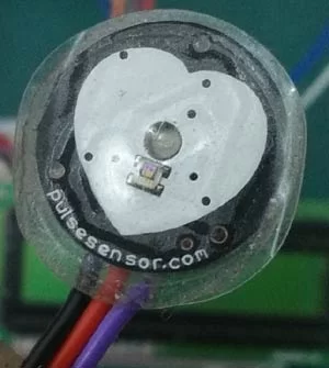
The sensor is really small and perfect for reading heartbeat across earlobe or on the fingertip. It is 0.625” in diameter and 0.125” thick from the round PCB side.
This sensor provides an analog signal and the sensor can be driven with 3V or 5V, the current consumption of the sensor is 4 mA, which is great for mobile applications. The sensor comes with three wire with 24” long hookup cable and berg male header at the end. Also, the sensor comes with Velcro Finger Strap to wear it across fingertip.
Pulse Sensor schematic is also provided by the manufacturer and also available on sparkfun.com.
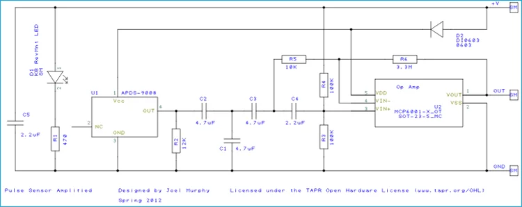
The sensor schematic consists optical heart-rate sensor, noise cancellation RC circuitry or filters, which can be seen in the schematic diagram. R2, C2, C1, C3 and an operational amplifier MCP6001 are used for reliable amplified analog output.
There are few other sensors for Heart Beat Monitoring but SEN-11574 pulse sensor is widely used in Electronics projects.
Circuit Diagram for Pulse Sensor interfacing with PIC Microcontroller
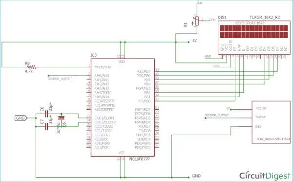
Here we have connected the pulse sensor across a 2nd pin of the microcontroller unit. As the sensor provides analog data, we need to convert the analog data into digital signal by doing necessary calculations.
The Crystal oscillator of 20Mhz is connected across two OSC pins of the microcontroller unit with two ceramic 33pF capacitors. The LCD is connected across the RB port of the microcontroller.
Code Explanation
The code is a little bit complex for beginners. The manufacturer provided sample codes for the SEN-11574 sensor, but it was written for the Arduino platform. We need to convert the calculation for our microchip, PIC16F877A. Complete code is given at the end of this project with a Demonstration Video.
Our code flow is relatively simple and we made the steps using a switch case. As per the manufacturer, we need to get the data from the sensor in every 2 milliseconds. So, we used a timer interrupt service routine which will fire a function in every 2 milliseconds.
Our code flow in switch statement will go like this:
Case 1: Read the ADC
Case 2: Calculate the Heart Beat and IBI
Case 3: Show the heartbeat and IBI on LCD
Case 4: IDLE (Do nothing)
Inside the timer interrupt function, we change the state of the program to Case 1: Read the ADC on every 2 milliseconds.
So, in the main function, we defined the program state and all the switch cases.
void main() {
    system_init();
    main_state = READ_ADC;
    while (1) {
        switch (main_state) {
            case READ_ADC:
            {
                adc_value = ADC_Read(0); // 0 is the channel number
                main_state = CALCULATE_HEART_BEAT;
                break;
            }
            case CALCULATE_HEART_BEAT:
            {
                calculate_heart_beat(adc_value);
                main_state = SHOW_HEART_BEAT;
                break;
            }
            case SHOW_HEART_BEAT:
            {
                if (QS == true) { // A Heartbeat Was Found
                    // BPM and IBI have been Determined
                    // Quantified Self "QS" true when Arduino finds a heartbeat
                    QS = false; // reset the Quantified Self flag for next time

                    // 0.9 used for getting better data. actually should not be used
                    BPM = BPM * 0.9;
                    IBI = IBI / 0.9;
                    lcd_com(0x80);
                    lcd_puts("BPM:-     ");
                    lcd_print_number(BPM);
                    lcd_com(0xC0);
                    lcd_puts("I.B.I:-   ");
                    lcd_print_number(IBI);
                }
            }
                main_state = IDLE;
                break;

        case IDLE:
        {
            break;
        }
        default:
        {

        }
    }
}
}
We are using two hardware peripherals of the PIC16F877A: Timer0 and ADC.
Inside the timer0.c file,
TMR0 = (uint8_t)(tmr0_mask & (256-(((2 *_XTAL_FREQ)/(256*4))/1000)));
This calculation is providing the 2 milliseconds timer interrupt. The calculation formula is
// TimerCountMax - (((delay(ms) * Focs(hz)) / (PreScale_Val * 4)) / 1000)
If we see the timer_isr function, it is-
void timer_isr() {
    main_state = READ_ADC;
}
In this function the program state is changed to READ_ADC in every 2ms.
Then the CALCULATE_HEART_BEAT function is taken from the Arduino example code.
void calculate_heart_beat(int adc_value) {
    Signal = adc_value;
    sampleCounter += 2; // keep track of the time in mS with this variable
    int N = sampleCounter - lastBeatTime; // monitor the time since the last beat to avoid noise

    //  find the peak and trough of the pulse wave
    if (Signal < thresh && N > (IBI / 5)*3) { // avoid dichrotic noise by waiting 3/5 of last IBI
        if (Signal < T) { // T is the trough
            T = Signal; // keep track of lowest point in pulse wave
        }
    }
………….
………………………..
Further, the complete code is given below and well explained by the comments. This heart beat sensor data can be further uploaded to the cloud and monitored over the internet from anywhere, which thus makes it IoT based Heart Beat Monitoring system, follow the link to learn more.
/*
* File: main.c
* Author: Sourav Gupta
* By:- circuitdigest.com
* Created on September 30, 2018, 2:26 PM
*/
// PIC16F877A Configuration Bit Settings
// ‘C’ source line config statements
// CONFIG
#pragma config FOSC = HS // Oscillator Selection bits (HS oscillator)
#pragma config WDTE = OFF // Watchdog Timer Enable bit (WDT disabled)
#pragma config PWRTE = OFF // Power-up Timer Enable bit (PWRT disabled)
#pragma config BOREN = ON // Brown-out Reset Enable bit (BOR enabled)
#pragma config LVP = OFF // Low-Voltage (Single-Supply) In-Circuit Serial Programming Enable bit (RB3/PGM pin has PGM function; low-voltage programming enabled)
#pragma config CPD = OFF // Data EEPROM Memory Code Protection bit (Data EEPROM code protection off)
#pragma config WRT = OFF // Flash Program Memory Write Enable bits (Write protection off; all program memory may be written to by EECON control)
#pragma config CP = OFF // Flash Program Memory Code Protection bit (Code protection off)
#include <xc.h>
#include <stdlib.h>
#include <stdio.h>
#include <string.h>
#include <stdbool.h>
#include “supporing_cfile\lcd.h”
#include “supporing_cfile\eusart1.h”
#include “supporing_cfile\adc.h”
#include “supporing_cfile\tmr0.h”
/*
Hardware related definition
*/
#define _XTAL_FREQ 200000000 //Crystal Frequency, used in delay
/*
Program Flow related definition
*/
#define READ_ADC 1
#define CALCULATE_HEART_BEAT 2
#define SHOW_HEART_BEAT 3
#define IDLE 0
#define DEFAULT -1
volatile int rate[10]; // array to hold last ten IBI values
volatile unsigned long sampleCounter = 0; // used to determine pulse timing
volatile unsigned long lastBeatTime = 0; // used to find IBI
volatile int P = 512; // used to find peak in pulse wave, seeded
volatile int T = 512; // used to find trough in pulse wave, seeded
volatile int thresh = 530; // used to find instant moment of heart beat, seeded
volatile int amp = 0; // used to hold amplitude of pulse waveform, seeded
volatile bool firstBeat = true; // used to seed rate array so we startup with reasonable BPM
volatile bool secondBeat = false; // used to seed rate array so we startup with reasonable BPM
volatile int BPM; // int that holds raw Analog in 0. updated every 2mS
volatile int Signal; // holds the incoming raw data
volatile int IBI = 600; // int that holds the time interval between beats! Must be seeded!
volatile bool Pulse = false; // “True” when User’s live heartbeat is detected. “False” when not a “live beat”.
volatile bool QS = false; // becomes true when finds a beat.
int main_state = -1;
int adc_value = 0;
int tune = 0;
/*
Other Specific definition
*/
void system_init(void);
void calculate_heart_beat(int adc_value) {
Signal = adc_value;
sampleCounter += 2; // keep track of the time in mS with this variable
int N = sampleCounter – lastBeatTime; // monitor the time since the last beat to avoid noise
// find the peak and trough of the pulse wave
if (Signal < thresh && N > (IBI / 5)*3) { // avoid dichrotic noise by waiting 3/5 of last IBI
if (Signal < T) { // T is the trough
T = Signal; // keep track of lowest point in pulse wave
}
}
if (Signal > thresh && Signal > P) { // thresh condition helps avoid noise
P = Signal; // P is the peak
} // keep track of highest point in pulse wave
// NOW IT’S TIME TO LOOK FOR THE HEART BEAT
// signal surges up in value every time there is a pulse
if (N > 250) { // avoid high frequency noise
if ((Signal > thresh) && (Pulse == false) && (N > (IBI / 5)*3)) {
Pulse = true; // set the Pulse flag when we think there is a pulse
IBI = sampleCounter – lastBeatTime; // measure time between beats in mS
lastBeatTime = sampleCounter; // keep track of time for next pulse
if (secondBeat) { // if this is the second beat, if secondBeat == TRUE
secondBeat = false; // clear secondBeat flag
int i;
for (i = 0; i <= 9; i++) { // seed the running total to get a realisitic BPM at startup
rate[i] = IBI;
}
}
if (firstBeat) { // if it’s the first time we found a beat, if firstBeat == TRUE
firstBeat = false; // clear firstBeat flag
secondBeat = true; // set the second beat flag
//pulse_tmr_handle = bsp_harmony_start_tmr_cb_periodic(PULSE_CHECK_TIME_INTERVAL, 0, pulse_read_cb); // enable interrupts again
return; // IBI value is unreliable so discard it
}
// keep a running total of the last 10 IBI values
uint16_t runningTotal = 0; // clear the runningTotal variable
int i;
for (i = 0; i <= 8; i++) { // shift data in the rate array
rate[i] = rate[i + 1]; // and drop the oldest IBI value
runningTotal += rate[i]; // add up the 9 oldest IBI values
}
rate[9] = IBI; // add the latest IBI to the rate array
runningTotal += rate[9]; // add the latest IBI to runningTotal
runningTotal /= 10; // average the last 10 IBI values
BPM = 60000 / runningTotal; // how many beats can fit into a minute? that’s BPM!
QS = true; // set Quantified Self flag
// QS FLAG IS NOT CLEARED INSIDE THIS ISR
}
}
if (Signal < thresh && Pulse == true) { // when the values are going down, the beat is over
Pulse = false; // reset the Pulse flag so we can do it again
amp = P – T; // get amplitude of the pulse wave
thresh = amp / 2 + T; // set thresh at 50% of the amplitude
P = thresh; // reset these for next time
T = thresh;
}
if (N > 2500) { // if 2.5 seconds go by without a beat
thresh = 530; // set thresh default
P = 512; // set P default
T = 512; // set T default
lastBeatTime = sampleCounter; // bring the lastBeatTime up to date
firstBeat = true; // set these to avoid noise
secondBeat = false; // when we get the heartbeat back
}
}
void main() {
system_init();
main_state = READ_ADC;
while (1) {
switch (main_state) {
case READ_ADC:
{
adc_value = ADC_Read(0);
main_state = CALCULATE_HEART_BEAT;
break;
}
case CALCULATE_HEART_BEAT:
{
calculate_heart_beat(adc_value);
main_state = SHOW_HEART_BEAT;
break;
}
case SHOW_HEART_BEAT:
{
if (QS == true) { // A Heartbeat Was Found
// BPM and IBI have been Determined
// Quantified Self “QS” true when arduino finds a heartbeat
QS = false; // reset the Quantified Self flag for next time
// 0.9 used for getting better data. actually should not be used
//BPM = BPM * 0.9;
// IBI = IBI / 0.9;
//IBI = IBI * 2;
// tune = BPM / 2;
//lcd_com(0x01);
lcd_com(0x80);
lcd_puts(“BPM:- “);
lcd_print_number(BPM);
lcd_puts (” “);
lcd_com(0xC0);
lcd_puts(“I.B.I:- “);
lcd_print_number(IBI);
lcd_puts (” “);
}
}
main_state = IDLE;
break;
case IDLE:
{
break;
}
default:
{
}
}
}
}
/*
This Function is for system initializations.
*/
void system_init(void){
TRISB = 0x00;
lcd_init(); // This will initialize the lcd
TMR0_Initialize();
TMR0_StartTimer();
INTERRUPT_GlobalInterruptEnable();
INTERRUPT_PeripheralInterruptEnable();
ADC_Init();
}
/*
* Custom timer callback function
*/
void timer_isr() {
main_state = READ_ADC;
}
void interrupt INTERRUPT_InterruptManager (void)
{
// interrupt handler
if(INTCONbits.TMR0IE == 1 && INTCONbits.TMR0IF == 1)
{
TMR0_ISR();
}
}
Video
Read More Detail:Heart Beat Monitoring using PIC Microcontroller and Pulse Sensor
- What is the primary function of the SEN-11574 pulse sensor in this project?
The sensor measures heartbeat across the earlobe or fingertip by providing an analog signal that is converted into digital data. - How does the system determine the time interval between beats?
The code uses a variable named IBI which tracks the time since the last beat to calculate the Inter-Beat Interval. - What frequency is required for the crystal oscillator in this circuit?
A 20Mhz crystal oscillator is connected across the OSC pins of the microcontroller unit. - How often does the timer interrupt service routine fire to read data?
The timer interrupt fires a function in every 2 milliseconds to ensure data is read regularly from the sensor. - Which port of the microcontroller is used to connect the LCD?
The LCD is connected across the RB port of the microcontroller. - What voltage can drive the pulse sensor?
The sensor can be driven with either 3V or 5V power supply. - How is the heartbeat data displayed to the user?
The calculated BPM and IBI values are shown on a 16x2 character LCD display. - What hardware peripherals of the PIC16F877A are utilized in this design?
The project uses Timer0 and ADC (Analog-to-Digital Converter) hardware peripherals. - What is the purpose of the 10K pot in this setup?
The 10K pot is used for contrast control of the LCD display. - Can this system be extended for IoT applications?
Yes, the heart beat sensor data can be uploaded to the cloud to create an IoT based Heart Beat Monitoring system.