


Summary of HD44780 16×2 Char LCD Interfacing with microcontroller
This project teaches interfacing and controlling an HD44780 16x2 character LCD: displaying "Hello Word!! LCD", using both 8-bit and 4-bit parallel modes, and creating custom characters. It covers pin functions, required initialization, key LCD commands (clear, home, entry mode, display on/off, cursor/display shift, function set, CGRAM addressing), and explains data transfer differences between 8-bit and 4-bit modes.Parts used in the HD44780 16x2 Char LCD Project:
- HD44780 16x2 character LCD module
- Microcontroller (unspecified)
- Power supply (+3V or +5V)
- Potentiometer for contrast (Vo)
- Wires for data and control lines (DB0–DB7, RS, R/W, E)
- LED backlight supply (A/Vee and K)
- Optional negative voltage or Vee source for contrast (if required)
Project Description:-
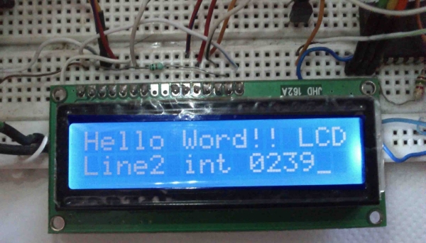
In this project we are going to learn various things about this chip set and displaying text on this LCD. The HD44780 16x2 char LCD screen Use 8bit and 4 bit parallel interface with backlight.
This Primary Objective in this project are:-
1. Displaying "Hello Word!! LCD " message on the scree.
2. Interfacing The LCD to the Microcontroller Using 8bit Mode and 4 Bit Mode.
3. Generating and Displaying Custom Char on the LCD Screen. clik here for custom char
Operation
as i have mentioned before this type of lcd are connected to microcontroller using parallel 8bit or 4bit lines.
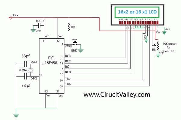
using 8 bit method is quite simple but take 8 lines (for data or command)+ 3 control signal total 11 line , i guess few small microcontrollers don't even have that much of I/O lines ,so in 4 bit mode total 7 lines (sometimes 6 ) are required . in this tutorial i will show you with both of the methods .
 Pin description
| PIN NUMBER | SYMBOL | FUNCTION |
| 1 | Vss | GND |
| 2 | Vdd | + 3V or + 5V |
| 3 | Vo | Contrast Adjustment |
| 4 | RS | H/L Register Select Signal |
| 5 | R/W | H/L Read/Write Signal |
| 6 | E | H → L Enable Signal |
| 7 | DB0 | H/L Data Bus Line |
| 8 | DB1 | H/L Data Bus Line |
| 9 | DB2 | H/L Data Bus Line |
| 10 | DB3 | H/L Data Bus Line |
| 11 | DB4 | H/L Data Bus Line |
| 12 | DB5 | H/L Data Bus Line |
| 13 | DB6 | H/L Data Bus Line |
| 14 | DB7 | H/L Data Bus Line |
| 15 | A/Vee | + 3.5V for LED/Negative Voltage Output |
| 16 | K | K Power Supply for B/L (OV) |
in 8 bit mode all the Data line DB0 to DB7 are being used for transferring the the data to lcd but in 4-bit mode only 4 line form DB4 to DB7 are being used to transfer the 8 bit wide data in two peaces one after another .
we can't display any data on the lcd until all the required internal command register of the lcd are not being properly initialized.
to know every thing about this lcd controller .. you can go through it's data sheet
click here to download HD44780 data sheet
so now we will learn how to initialize the lcd.
LCD Commands
Clear Display
clear and place the cursor in the first position (address 0). The bit I / D to 1 by default.
| RS | R / W | DB7 | DB6 | DB5 | DB4 | DB3 | DB2 | DB1 | DB0 |
| 0 | 0 | 0 | 0 | 0 | 0 | 0 | 0 | 0 | 1 |
Return the cursor to Home
Place the cursor in the home position (address 0) and make the display starts to move from its original position. The contents of the RAM display data (DD RAM) remains unchanged. The address of the RAM for display data (DD RAM) is set to 0.
| RS | R / W | DB7 | DB6 | DB5 | DB4 | DB3 | DB2 | DB1 | DB0 |
| 0 | 0 | 0 | 0 | 0 | 0 | 0 | 0 | 1 | X |
Entry Mode in Set
Set cursor moving direction and specify that the display moves to the next position of the screen or not. These operations are performed during reading or writing of the DD RAM or CG RAM. To view usually set bit S = 0.
| RS | R / W | DB7 | DB6 | DB5 | DB4 | DB3 | DB2 | DB1 | DB0 |
| 0 | 0 | 0 | 0 | 0 | 0 | 0 | 1 | I / D | S |
Display ON / OFF Control
Turn on or off by turning ON / OFF both the LCD (D) as the cursor (C) and whether or not this last flash (B).
| RS | R / W | DB7 | DB6 | DB5 | DB4 | DB3 | DB2 | DB1 | DB0 |
| 0 | 0 | 0 | 0 | 0 | 0 | 1 | D | C | B |
Cursor or Display Shift
Move the cursor to move the LCD without changing the memory contents of the display data DD RAM.
| RS | R / W | DB7 | DB6 | DB5 | DB4 | DB3 | DB2 | DB1 | DB0 |
| 0 | 0 | 0 | 0 | 0 | 1 | S / C | R / L | X | X |
 Function Set
Set the size of interface with the data bus (DL), number of lines in the LCD (N) and character type (F).
| RS | R / W | DB7 | DB6 | DB5 | DB4 | DB3 | DB2 | DB1 | DB0 |
| 0 | 0 | 0 | 0 | 1 | DL | N | F | X | X |
Set the CG RAM Address
The LCD module defined in addition to all the ASCII character set allows the user to define 4 or 8 characters. The composition of these characters is saved to a CG RAM memory called up to 64 bytes. Each user defined character consists of 16 or 8 bytes that are stored in successive positions of the CG RAM.
Using this instruction sets the CG RAM memory address from which the bytes will be stored that define a character. Running this command all the data that is subsequently read or write this memory made from CG RAM.
For more detail: HD44780 16x2 Char LCD Interfacing with microcontroller
- What is the primary objective of this project?
To display Hello Word!! LCD, interface the LCD in 8-bit and 4-bit modes, and generate/display custom characters. - How many pins does the HD44780 16x2 LCD have and what are their main functions?
It has 16 pins: power (Vss, Vdd), contrast (Vo), control (RS, R/W, E), data bus DB0–DB7, and backlight A/Vee and K. - Can the LCD be used in 4-bit mode and why use it?
Yes; 4-bit mode uses DB4–DB7 to send 8-bit data in two nibbles and reduces I/O lines needed on the microcontroller. - How is data transferred in 8-bit mode?
All data lines DB0–DB7 are used to transfer full 8-bit data in one operation. - Do you need to initialize the LCD before displaying data?
Yes; you must properly initialize the LCD internal command registers before displaying any data. - How many custom characters can be defined and where are they stored?
You can define 4 or 8 custom characters stored in CG RAM up to 64 bytes. - What command clears the display and where does the cursor go?
The Clear Display command clears the screen and places the cursor at address 0. - What does the Function Set command configure?
It sets interface data length (DL), number of display lines (N), and character font (F).
Related projects
CAN FD Node based on a PIC18 Microcontroller
The introduction sets the stage for an embedded systems project that involves developing a Embedded C CAN FD project using the MCP2517FD...
Communication & InterfacingLAN9662 Gigabit Switch: Optimized for Industrial Ethernet
Introduction It should come as little surprise therefore that one element of what is now more commonly referred to in some circles...
Communication & InterfacingPIC Microcontroller: Fundamentals & Applications for Students
Introduction Microcontrollers are the key components in the embedded systems market. A variety of embedded systems was formed and developed after the...
Communication & Interfacing10BASE-T1S Ethernet: Simplified OEM Design for Auto Devices
Introduction Cars these days are surrounded by technology. They come loaded with all sorts of electronic gadgets and sensors. This project wants...
Communication & InterfacingDesigning a Microcontroller Framework for PC-Based Control of Electrical Appliances
ABSTRACT The preference for personal computers as a platform for designing and implementing control algorithms is growing due to the ease of...
Communication & InterfacingEfficient Multichannel Data Acquisition with USB Connectivity using PIC Microcontroller
1. INTRODUCTION With the rapid advancements in embedded technology, there is a growing demand for a data acquisition system that combines fast...

Ibrar Ayyub
I am an experienced technical writer holding a Master's degree in computer science from BZU Multan, Pakistan University. With a background spanning various industries, particularly in home automation and engineering, I have honed my skills in crafting clear and concise content. Proficient in leveraging infographics and diagrams, I strive to simplify complex concepts for readers. My strength lies in thorough...