
Summary of GSM Based Digital Wireless Notice Board Using PIC16F877A Microcontroller
This project implements an intelligent GSM-based notice board using a PIC16F877A microcontroller. SMS messages received by a GSM modem are parsed for content enclosed between $ signs and displayed on a 16x2 LCD; the system initializes the modem to text mode, shows status messages, updates the display when new SMS arrives, and provides an audio indicator via a buzzer. The design uses PORTB in 4-bit LCD mode and stores incoming message text in an INFO array for display.
Parts used in the GSM Notice board using PIC16F877A:
- PIC16F877A
- Transistor BC548
- Resistors 1KΩ
- Resistors 10KΩ
- POT 10K
- Capacitors 33pF (two)
- Capacitor 10µF
- Crystal 11.0592MHz
- LCD 16×2
- GSM Modem
- Push button
- Buzzer
Are you looking for Final year Electronics Engineering Project? Here CircuitsGallery presents GSM based electronics and telecommunication engineering projects for students. You can submit this as your academic project. Our project is nothing but a GSM based notice board using PIC that is capable of displaying SMS received by it. You can specify what content that you would like to display on the noticeboard by the SMS. The main component of the GSM Notice board is PIC16F877A, received message is displayed on the LCD display which will update automatically when next SMS is received, it has audio indicator to inform that SMS is received. This is an intelligent noticeboard intended as electronics engineering projects for final year students.
 Get your final year project score maximum with our Intelligent GSM Notice board using PIC16F877A.
Definitely electronics change our life and this one is the best examples for that. Now let’s begin the technical steps to be carried out for building this GSM Notice board using PIC16F877A.
Components Required for GSM Notice Board Using PIC Microcontroller
- PIC16F877A
- Transistor BC548
- Resistor (1KΩ, 10KΩ)
- POT (10K)
- Capacitor (33pfx2, 10µF)
- Crystal (11.0592MHz)
- LCD 16×2
- GSM Modem
- Push button
- Buzzer
Working of GSM Notice Board
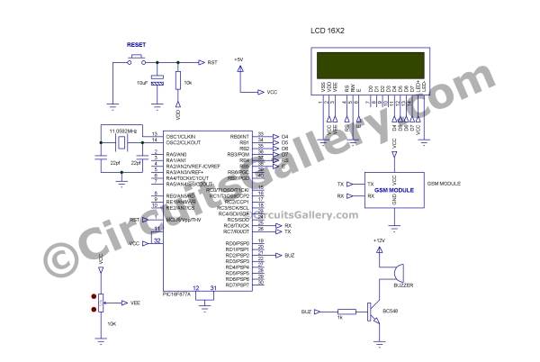
- GSM Modem is used to receive SMS, which is controlled by PIC.
- When the system is ON then PIC will initialize GSM, by sending commands to make the modem in text mode.
- Same time it controls display which is connected on PORTB in 4 bit mode.
- LCD display shows “GSM is initializing“, after initialization it show “Waiting for SMS“.
 When a message is received GSM module starts with this kind of format CMT:[Mob No]:[time]: [Message].
- After detecting CMT it waits to receive ‘$’, I used ‘$’ sign to indicate starting of the message that is to be displayed on the notice board, because GSM modem sends more data which includes received message time, sender number etc. like CMT:[Mob No]:[Time]:[Message].
- For our simplicity I used ‘$’ to enclose the message so our message will be [$ Message content $]. PIC will filter them between two ‘$’ signs.
- The default infinite loop will break only when ‘$’ sign is received, after receiving ‘$’ it stores the content of the message on the array named as INFO.
For more detail: GSM Based Digital Wireless Notice Board Using PIC16F877A Microcontroller
- What microcontroller is used in the GSM notice board project?
The project uses the PIC16F877A microcontroller. - How does the system receive messages to display?
The system receives SMS messages using a GSM modem controlled by the PIC. - How are messages identified for display on the notice board?
Messages to display are enclosed between two $ signs and the PIC filters text between those $ signs. - How is the LCD connected to the PIC?
The LCD is connected to PORTB of the PIC and operated in 4-bit mode. - What status messages does the LCD show during startup?
The LCD shows GSM is initializing and then Waiting for SMS during startup and initialization. - How does the PIC initialize the GSM modem?
The PIC sends commands to set the GSM modem to text mode at system startup. - Does the system provide an alert when a new SMS is received?
Yes, the system includes a buzzer as an audio indicator to inform that an SMS is received. - Where is the received message stored before display?
The received message content is stored in an array named INFO before being displayed.
