Summary of Getting Started With Proteus
Proteus tutorial introduction explaining its primary uses: PCB design and code testing, not perfect circuit simulation. The post outlines Proteus ISIS interface sections, key toolbar functions (new/open/save, ARES for PCB), component selection (Component Mode, P button, search), power/ground placement, visualization tools (oscilloscope, virtual terminal, signal generator), graph/voltage/current probes, custom component design, and text annotation. Emphasizes verifying circuits on hardware and using Proteus mainly for PCB layout and debugging code before programming microcontrollers.
Parts used in theGetting Started with Proteus:
- Proteus ISIS software (installed, registered version)
- Toolbar (new, open, save, zoom, ARES icon)
- Component Mode icon
- P button (Part list)
- E button (Edit properties)
- Component search textbox
- Power and Ground components (default +5V)
- Oscilloscope
- Virtual Terminal
- Signal Generator
- Graph mode
- Voltage probe
- Current probe
- Component Designer (for custom components)
- Text annotation tool
Hello readers, today’s post is the first regular post on Proteus tutorial. In today’s tutorial, I am gonna share Getting Started with Proteus. Today’s tutorial is for beginners who don’t have much knowledge of Proteus but wants to start working with it. We don’t design any circuit in today’s post instead we will check the different functions of Proteus which provides ease in circuit designing. Proteus has different functions in it and in order to design a circuit, one must have sound knowledge of each of them.

I have divided this tutorial in ten parts and today we will discuss the first part of this tutorial. Even if you know the know how of Proteus but still I will suggest you to read this tutorial for once, so that you could understand what is Proteus and what is its best use? So, let’s have a look at Getting Started with Proteus:
Actual Use of Proteus
Usually, I got many such questions from the students that our circuit is working perfectly on proteus but when we have implemented it on hardware, it’s not working. That’s why I am first explaining the use of Proteus here.
- Never trust the circuit you design on Proteus. Proteus is very lenient in circuits designing and it works on ideal conditions like if you don’t add pull up resistors etc in the proteus then it wont bother at all and runs the circuit.
So, as the circuit designing is concerned you must have sound knowledge of components, only then you can design a working circuit. So, now the question arises what’s the use of proteus then ???
- The main and foremost use of Proteus is the PCB designing.
In normal practice, I myself first design the circuit on either the wero board or the bread board and then when I got sure that my circuit is fully working then I design its PCB in the proteus.
- Second use of Proteus is the Code Checking.
When you are designing some code like writing some strings on the LCD then its quite annoying to burn the microcontroller several times. Instead, design a circuit in your Proteus and after that simply design your PIC code and then run it on Proteus and get your best result and now when you are sure you are getting perfect output then burn your PIC and test it on your hardware. Quite easy and handy. In the coming classes, I will show you how to burn code in microcontrollers in Proteus.
Note: In testing of code, there’s again a possibility that your output on hardware doesn’t match with that of Proteus but its quite rare and mostly happens in delays.
Getting Started With Proteus
So now let’s have a look at different features Proteus offers. I have a full registered version of Proteus but I can’t post it here as its not allowed so if someone need it then Subscribe to our mailing list and post your subscribed emails in the comments below and I will send it to you. So now I suppose you have installed Proteus and ready to work on it.
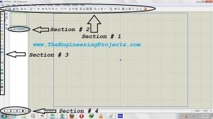
- Click on Proteus ISIS and it will be appear as shown in image below. Right click the image and open in new tab to get a better look of the image. In the central area, we design our circuit i.e. place the components and then join them.

- In the below image, I have divided the Proteus in several sections. Section 1 is a toolbar which you have seen on many software, it has simple functionality like first icon on the toolbar is to create a new layout, second is to open an existing layout, next one is to save your layout, then there comes few zooming options and also some tools which we will further discuss in next tutorials and at the end of section 1, you can see ARES icon and we will also see its use when we will design the PCB layout.
- Let’s come to section 2, it has two buttons on it, one is P and other is E. P changes with the selection change of section 3 mostly it is used for opening the part list i.e component list and E is used for editing purposes, like you want to edit the properties of any component then simply click on that component and then click on E and it will open the properties of that component and you can easily edit it.
- Section 3 is most commonly used section of proteus. It has a lot of functions on it. We will check them today one by one in complete detail.
- Now finally the section 4, this section shows different buttons like play, stop etc. When you design some circuit in Proteus, then you want to run it in order to check whether its working or not. So in order to run the circuit, you have to click on this play button. So when you click on play button the circuit starts to run, now click on Pause button and it will pause and Stop to stop the circuit running.
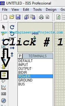
- Now let’s discuss the section 3, one by one. In the below image you can see the icon on which I have written Click # 1.When you click on this icon, your Proteus goes in the component state. We select components by clicking this icon. Suppose I want to use PIC16F877A in my circuit so what will I do, I will click on this Component Mode Icon and then Click on the P button and a new window will open up as shown in the below figure.
- In this new window there’s a textbox on which Keyword is written, this text box is used for the component search. Proteus database has unlimited components in it so now in order to get your desired component, you have to search for it as I did.
- I have search PIC16F877A and proteus automatically show me that component as you can see below and not only the component name but also its preview in the top right corner and then the PCB preview as well. Unfortunately my Proteus doesn’t have the PCB preview of PIC16F877A that’s why it is showing blank.
- So after you are sure that you have selected the right component, either double click on it or click on the OK button as shown in figure below.
- If I just want to search one component then I will click OK but its not mostly the case as in circuit design, as we will see in our next classes, we have to add a lot of components so what we do is we simply search our component in text box and double click on it and then search the next component and so on.
![]()
- Now move to next icon as shown in figure below. This is also another most commonly used icon in Proteus. As you can see when you click on it the white are shows few options. In circuit designing, there are lot of components which are getting with ground or power up, so if we are gonna add wires for each of them then it got quite messy.
- Proteus provide a very easy way of doing it. Ground and Power , as shown below, are treated as component so wherever we need GND we simply pick the Ground from here and place it there and same for the Power. Default value of this Power is +5V.
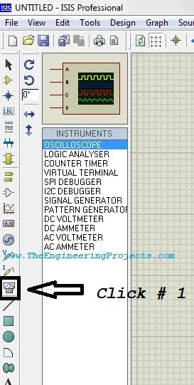
- The icon shown in the below figure also used quite often. It has many components which are very useful and this section is used for visualization. Like there’s an oscilloscope, we use it for viewing the behavior of different signals generated. Its as same as an oscialloscope you found in your lab.
- Another important component of this mode is the Virtual Terminal, it is shown on the fourth number. This Virtual Terminal is used for checking data coming through Serial Port. Its just like the hyper terminal we have in our windows.
- Then there’s Signal Generator, it is used to generate signal like sine wave of desired frequency.
- You can test them by yourself to get a better idea.
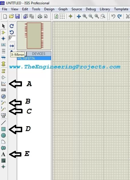
- Now, let check few of them quickly, the icon which I have shown by A is the Graph mode. Like in some circuit you want to analyze the graphs of voltage and current then you can do this using the graph mode, it has different style of graphs. We will also add a tutorial in which we will see how to make graphs.
- B and C in the below figure are the voltage and current probes respectively. Suppose you have designed some circuit in Proteus and now you want to check the value of voltage at any point in the circuit. In order to do so, simply select this voltage probe and place it there and when you run your circuit, the probe will show the value of voltage above it and same for current probe.
- D has lots of functionality, it is used when we want to design our own component in Proteus.
- E in the below figure is simply text section, like you want to add some text indication you use this one.
- So today, we have checked the Getting started with Proteus, hope you find this post informative. If you have any question feel free to ask in comments and also subscribe through email to our mailing list so that you don’t miss any part of this tutorial. Stay blessed. Take care.
- What is the main use of Proteus?
The main use of Proteus is PCB designing, and it is also useful for code checking before burning microcontrollers. - Can I trust Proteus simulations to work identically on hardware?
No, Proteus runs on ideal conditions and may not reflect real hardware; never fully trust a Proteus-only design. - How does Proteus help with code testing?
You can run your microcontroller code in Proteus to check outputs like LCD strings before burning the PIC into hardware. - What is the Component Mode and how do I select parts?
Component Mode lets you pick components; click the mode, press P to open the part list, search in the textbox, then double click or OK to add. - How do I add power and ground in Proteus?
Power and ground are treated as components; pick them from the mode that lists Power and Ground and place them where needed (Power defaults to +5V). - Which tools help visualize signals in Proteus?
Proteus includes an oscilloscope, virtual terminal, signal generator, and graph mode for visualizing signals and data. - How can I measure voltage or current at a point in Proteus?
Use the voltage probe and current probe components; place them at desired points and run the circuit to view values. - What is the E button used for?
The E button is used to edit properties of a selected component by opening its properties dialog. - What is ARES in the Proteus toolbar?
ARES is the PCB design module referenced on the toolbar for designing PCB layouts from your circuit. - Can I create custom components in Proteus?
Yes, Proteus includes a Component Designer mode used to design custom components.