


Summary of Generating PWM with PIC Microcontroller using CCP Module
This article explains how to generate Pulse Width Modulation (PWM) signals using the Capture/Compare/PWM (CCP) modules of a PIC 16F877A microcontroller with MikroC Pro. It details essential library functions for initialization, starting, stopping, and adjusting duty cycles via software. The tutorial demonstrates controlling two PWM outputs using four switches connected to PORTD, allowing users to increment or decrement duty ratios in real-time, with outputs observable on an oscilloscope or LEDs.Parts used in Generating PWM with PIC Microcontroller:
- PIC 16F877A Microcontroller
- MikroC Pro for PIC Microcontroller Software
- Four Switches
- CRO (Oscilloscope)
- Two LEDs (Optional)
- Timer 2 Module
CCP Modules are available with a number of PIC Microcontrollers. CCP stands for Capture/Compare/PWM. Using PWM module is far more easier and cost effective than using extra chips for PWM generation. MikroC Pro for PIC Microcontroller provide built-in library for PWM which makes our task very simple.
MikroC Functions
- PWM1_Init(constant long frequency) : This function initializes the PWM module with duty ratio 0. Frequency parameter is the desired frequency in Hz. It should be a numeric constant, should not be a variable.
- PWM1_Set_Duty(unsigned short duty_ratio) : This function is used to set the duty cycle of the PWM. The parameter duty_ratio takes values from 0 to 255, ie 0 means 0% , 127 means 50% and 255 means 100% duty cycle. The PWM1_Init() routine must be called before using this.
- PWM1_Start() : This function starts the PWM output. PWM1_Init() must be called before calling this routine,
- PWM1_Stop() : This function stops the PWM output. PWM1_Init() must be called before calling this routine. PWM1_Start() should be called before calling this function otherwise calling this function will not have any effect as PWM module is not running.
Note 1 : For microcontrollers with more than one CCP module, to use the desired CCP module for PWM generation simply change the number “1” in the prototype with desired module number. eg: PWM2_Init(5000), PWM2_Start().
Note 2 : All PWM modules in a PIC Microcontroller uses Timer 2 for its operation, so you cannot set different frequencies for different PWM modules.
In this tutorial we are using PIC 16F877A for demonstrating PWM generation using CCP module. PIC 16F877A contains two CCP modules.
Circuit Diagram – Using internal PWM Module of PIC
In the below circuit four switches are provided for controlling the Duty Ratio of PWM generated by two CCP modules of the PIC Microcontroller.
- Switch 1 : To increase the Duty Ratio of PWM produced by CCP1
- Switch 2 : To decrease the Duty Ratio of PWM produced by CCP1
- Switch 3 : To increase the Duty Ratio of PWM produced by CCP2
- Switch 4 : To decrease the Duty Ratio of PWM produced by CCP2
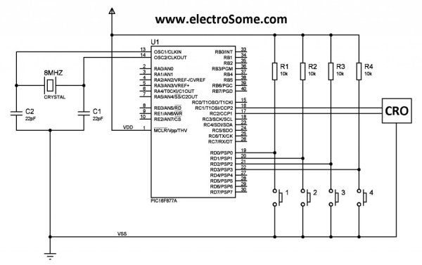
The output of the two CCP modules are given to a CRO to observe the changes in pulse width. It may be given to two LEDs and you can see the changes in brightness as Duty Ratio changes.
MikroC Program
void main()
{
  short current_duty_1  = 16; // initial value for current_duty_1
  short current_duty_2 = 16;  // initial value for current_duty_2

  TRISD = 0xFF; // PORTD as input
  TRISC = 0x00; // PORTC as output

  PWM1_Init(5000);  // Initialize PWM1
  PWM2_Init(5000);  // Initialize PWM2

  PWM1_Start();  // start PWM1
  PWM2_Start();  // start PWM2

  PWM1_Set_Duty(current_duty_1); // Set current duty for PWM1
  PWM2_Set_Duty(current_duty_2); // Set current duty for PWM2

  while (1)        // endless loop
  {
     if (!RD0_bit)   // if button on RD0 pressed
     {
      Delay_ms(40);
      current_duty_1++;  // increment current_duty_1
      PWM1_Set_Duty(current_duty_1);  //Change the duty cycle
     }

    if (!RD1_bit)               // button on RD1 pressed
    {
      Delay_ms(40);
      current_duty_1--;  // decrement current_duty_1
      PWM1_Set_Duty(current_duty_1);
     }

    if (!RD2_bit)     // if button on RD2 pressed
    {
      Delay_ms(40);
      current_duty_2++;    // increment current_duty_2
      PWM2_Set_Duty(current_duty_2);
     }

    if (!RD3_bit)       // if button on RD3 pressed
    {
      Delay_ms(40);
      current_duty_2--;   // decrement current_duty_2
      PWM2_Set_Duty(current_duty_2);
     }

    Delay_ms(10);      // slow down change pace a little
  }
}
I thinks the program is self explanatory, so if you have any doubts please comment below…
Download
You can download the MikroC Source Code, Proteus files etc here…
Video
Source : Generating PWM with PIC Microcontroller using CCP Module
Quick Solutions to Questions related to Generating PWM with PIC Microcontroller:
-
How is PWM generated in this project?
PWM is generated using the CCP modules available in PIC Microcontrollers instead of extra chips. -
What function initializes the PWM module?
The function PWM1_Init takes a numeric constant frequency parameter in Hz to initialize the module. -
How do you set the duty cycle value?
You use PWM1_Set_Duty with a value between 0 and 255, where 0 is 0%, 127 is 50%, and 255 is 100%. -
Can different frequencies be set for different PWM modules?
No, all PWM modules in a PIC Microcontroller use Timer 2, so they cannot have different frequencies. -
Which ports are configured as input and output in the code?
PORTD is configured as input and PORTC is configured as output. -
How does the program increase the duty ratio?
Pressing the switch on RD0 increments the current_duty_1 variable and updates the duty cycle. -
What happens if PWM1_Start is not called before PWM1_Stop?
Calling PWM1_Stop without calling PWM1_Start first will have no effect because the module is not running. -
How can you observe the changes in pulse width?
The output can be connected to a CRO to observe pulse width changes or to two LEDs to see brightness changes.
Related projects
Real-Time CAN-Based Vehicle Monitoring System with PIC MCU
INTRODUCTION The Controller Area Network (CAN) is a robust vehicle communication bus standard that was primarily developed for automobile applications but has...
Motors & RoboticsEasy Way to Learn Robotics Using Microcontrollers: A Beginner’s Guide
The title, "Easy Way to Learn Robotics Using Microcontrollers," promises an accessible entry point for those curious about the exciting world of...
Motors & Robotics · PIC16F877AEfficient Sun-Following Robot: A Solar Tracker with Microcontroller Control
Abstract The impending global challenge of dwindling non-renewable fuel resources underscores the urgency of transitioning towards renewable energy alternatives like solar power....
Motors & RoboticsInnovative Robotics: A Comprehensive Project Exploration
A DC motor functions as an electromechanical device, translating electrical signals into mechanical movements. The rotation of the motor correlates directly with...
Motors & RoboticsAdvanced Techniques for Fault Detection, Indication, and Protection in Induction Motors
1. INTRODUCTION The impact of microcontroller usage on our daily lives is remarkable. This versatile device is now prevalent in various control...
Motors & RoboticsExploring Versatility: GSM-Based Robotic Vehicle Technology
Introduction To Robotics The term 'Robot' remains elusive, defying a precise definition due to its evolving usage. Initially, it referred to humanoid...

Ibrar Ayyub
I am an experienced technical writer holding a Master's degree in computer science from BZU Multan, Pakistan University. With a background spanning various industries, particularly in home automation and engineering, I have honed my skills in crafting clear and concise content. Proficient in leveraging infographics and diagrams, I strive to simplify complex concepts for readers. My strength lies in thorough...