Summary of Frequency counter with PIC16F628A
This project builds a frequency counter around the PIC16F628A by merging an LCD-based design with a 6-digit 7-segment LED counter. The author adapts the PIC despite limited I/O by multiplexing the display and using a transistor to drive one common cathode, enabling a full 6-digit 7-segment readout with minimal extra components.
Parts used in the Frequency counter with PIC16F628A:
- PIC16F628A microcontroller
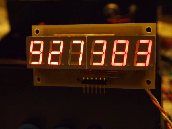
- 6-digit 7-segment LED display (common cathode)
- Crystal oscillator (for PIC)
- Transistor (to drive one common cathode)
- Signal input connector
- Resistors (for segment current limiting and transistor base)
- Capacitors (for oscillator and decoupling)
- Power supply (Vcc and ground connections)
This is a frequency counter based on PIC16F628A. The original idea came from this project: LCD frequency counter. As you can see – very simple and yet elegant schematic. But I wanted to use 7-segment LED display, not LCD, so I found a second useful project: Simple 100MHz frequency counter which uses 6 digit LED display.
| Schematic |
|
|
Combining two projects into one wasn’t very easy. First of all I wanted a PIC microcontroller to do the whole job without any additional ICs. Also I wanted to use the the familiar 16F628A, but because one of the portA pins (RA5) can be used only as input I was short of outputs to do the job. Driving 6 digit 7-segment multiplexed display requires 7 + 6 = 13 outputs. The 16F628A has 16 IO pins, two of which are used for the crystal oscillator, one is for the signal input and other one can be used only for input, that leaves us with only 12 useful IO pins. The solution was to drive one of the common cathodes with a transistor, which opens when all other digits are switched off.
For more detail: Frequency counter with PIC16F628A
- What microcontroller is used in the project?
The project uses a PIC16F628A microcontroller. - Does the design use an LCD or LED display?
The adapted design uses a 6-digit 7-segment LED display instead of an LCD. - How many I/O pins are required to drive the 6-digit 7-segment display?
Driving the 6-digit 7-segment multiplexed display requires 13 outputs (7 segment lines plus 6 digit selects). - How does the project overcome the PIC16F628A I/O pin shortage?
It multiplexes the display and uses a transistor to drive one common cathode, reducing required PIC outputs. - Is an additional IC required to drive the display?
No additional driver IC is used; the PIC and a transistor handle the display drive. - Which pin limitations of the PIC16F628A affected the design?
Two pins are used by the crystal oscillator, one for signal input, and RA5 is input-only, leaving only 12 usable I/O pins. - What role does the transistor play in the circuit?
The transistor drives one of the common cathodes and is enabled when other digits are switched off to save I/O lines. - Does the project support frequencies up to 100 MHz?
The project references a Simple 100MHz frequency counter as the LED-based inspiration, indicating high-frequency capability in the combined approach.