


Summary of PIC Projects using pic microcontroller
The article discusses the author's experience with various Microchip PIC microcontrollers, focusing on the 16F84 for its extensive documentation and homebrew programmer availability. It details a project involving an LCD display using the Hitachi HD44780 chipset, highlighting a 4-bit interface wiring scheme with specific protection components like capacitors and resistors. The author also reviews the P16PRO40 programmer kit and the Hi-Tech C compiler, noting its configuration commands and limitations in the student version.Parts used in the PIC Projects:
- PIC16F84 chip
- PIC16F876 chip
- PIC16F877 chip
- LCD with Hitachi HD44780 chipset
- 10MHz resonator with built-in caps
- Bi-color LED (Red/Green)
- P16PRO40 Programmer Kit
- Zero Insertion Force (ZIF) Socket
- Capacitor for pin 5
- 4.7K limiting resistor for pin 4
- Hi-Tech C Compiler
-
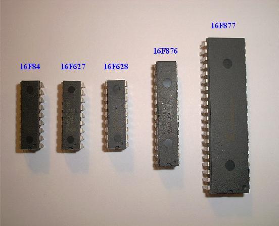
Some of the various PICs from Microchip, 16F84, 16F627, 16F628, 16F876 and a 16F877.
- So far, I have only played around with the PIC16F84 PIC chip, with exception to using a PIC16F876 with the HamHUD. I have found the most documentation is on the 16F84. I have also found the most homebrew programmers for this PIC. I am starting to use 16F877 PICS now for larger projects. I mainly have to write for these in another compiler other than Hi-Tech's because I do not have a full registered version ($850). Below, I have posted a pinout diagram I created in MS Paint. I usually get most of my PICs and ocillators from Digi-Key
 It's fun to make the PIC do simple things like making LEDs blinks and related projects, but I like to do more exciting things, like using an LCD. If programmed right, the 16F84 can be a very usefull in many different applications. Below is another pinout I created to show the 14 pin serial/power inputs for the LCD. It uses an industry standard chipset (Hitachi HD44780). Any LCD using this chipset can be used. A great source of cheap, high quality LCDs is Crystalfontz
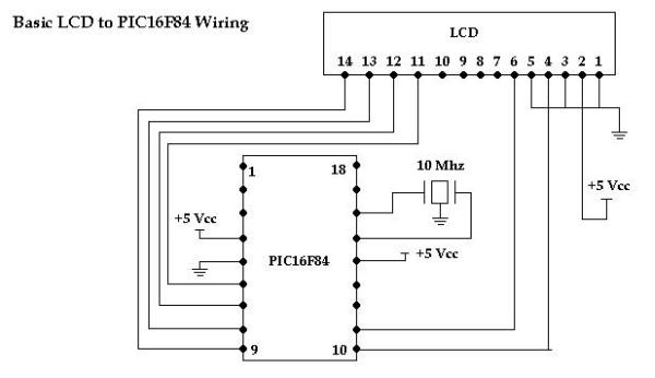
- Here is the basic wiring for an LCD to a PIC16F84. This is the most basic wiring diagram. This is a 4 bit interface. It uses PORT B pins 0-3 for the data input. Most engineers like to add a cap at pin 5 of the PIC and take the PIC side of the cap to ground. Also adding a 4.7K limiting resistor to pin 4 of the PIC can help from voltage jolts, I personally have not experienced this. This circuit has much design flexability and a lot can be added if wanted. Mosty protection components.
- Here is the programmer I use to program my PICs. It's called the P16PRO40. This was a cheap programmer kit that only cost me $25. The programmer itself was about $15 but I opted for the extra ZIF socket (Zero Insertion Force Socket) which cost about another $6 or so, plus shipping brought it up to about $25. It can be found at Amazon Electronics. It's under the Soldering Required Kits - Microcontrollers and Programmers. This programmer will program almost every PIC out there.
HI-Tech's C compiler
- I have started to use a C compiler for PIC programming provided by www.htsoft.com. It's a demo or student version that is not limited to function as far as programming commands but it will only allow for code to be written for the 16F84 and 16C84 PICs.
- So far I have not had much luck since this type of C programming is completely new to me. It is NOT C++, not even close if you ask me. HTLPIC sets up differently from other PIC C compilers. It requires more lines of set-up code at the top of the program file.
- Such as, __CONFIG(x), this command tells the compiler what configuration to load for the particular processor. In this case we are talking about the 16F84, so __CONFIG(0xnnnn) is the configuration command required. This command is unique to the particular processor.
- The CONFIG word determines what initial features are activated on the PIC, such as, Watchdog Timer, Code Protection, What type of occillator. The the configuration word is represented in HEX
- The syntax is very basic: __CONFIG(0xnnnn); //nnnn being the HEX value
- Some examples: __CONFIG(0x3FF1);
- This was my first sucessful project with a PIC chip. I used a 16F84 with a 10MHz resonator with built in caps.
- Click here to view the source code to this project. The code is written in Hi-Tech C.
- Click here to download the source code to this project. File has a ".c" extension.
- Here is a neat PIC project that I created using the 16F84 chip and a neat little bi-color LED from Radio Shack. The LED can be red or green depending on the bias of the diode. By using two of the PORT B pins, I can control the bias of the LED. If the LED is on PORT B, Pin 0 and Pin 1, I can set Pin 0 HIGH and Pin 1 LOW, this would make the LED light red. If Pin 0 is set LOW and Pin 1 is set HIGH, the LED will light green. PORT B has 8 pins, so I was able to connect up to 4 LEDs and have full control of them all (as seen in the schematic).
For more detal: PIC Projects
-
Which PIC chip has the most documentation available?
The PIC16F84 has the most documentation and homebrew programmers available. -
What is the cost of the P16PRO40 programmer kit including shipping?
The total cost including shipping was about $25. -
Which LCD chipset is used in the described project?
The project uses an industry standard Hitachi HD44780 chipset. -
How can you control a bi-color LED to light red or green?
Set Pin 0 HIGH and Pin 1 LOW for red, or set Pin 0 LOW and Pin 1 HIGH for green. -
What command sets the configuration word in Hi-Tech C?
The command __CONFIG(x) is used to tell the compiler what configuration to load. -
Why does the author use a different compiler for the 16F877?
The author uses another compiler because they do not have a full registered version of Hi-Tech which costs $850. -
What protection components are recommended for the PIC circuit?
A capacitor at pin 5 and a 4.7K limiting resistor to pin 4 are recommended. -
Where can one find cheap high quality LCDs mentioned in the text?
Crystalfontz is suggested as a great source for cheap high quality LCDs.
Related projects
PIC Stepper Motor Controller using PIC16F84A with Proteus Simulation
Introduction Stepper motors are widely used in embedded systems and DIY electronics projects where precise position control is required. This PIC Stepper...
Programmers & ICSP · PIC16F84APIC Musical Doorbell using PIC16F84A with Proteus Simulation
IntroductionThis microcontroller project demonstrates a musical doorbell built around a PIC16F84A and a simple piezo sounder.Using two push buttons, the system allows...
Beginner Tutorials · PIC16C84Exploring the World of PIC Microcontrollers: An Architectural Overview
A Peripheral Interface Microcontroller (PIC), developed by General Instruments Microcontrollers in 1993, operates under software control and is programmed to execute various...
LED ProjectsAn Application-Driven Microcontroller Curriculum
Understanding how to apply microcontrollers lies at the core of modern embedded systems education. This student project takes an experiential approach to...
LED ProjectsBuild this microcontroller controlled rainbow flying disc – and then throw it!
Hello all and welcome to this super simple and inexpensive instructable. If you like throwing frisbees AND you like flashing lights AND...
LED ProjectsLED Scrolling Display Project Working With Circuit Diagram
We normally use a simple static LED display screen to convey a message. Earlier, when we want to display large data, we...

Ibrar Ayyub
I am an experienced technical writer holding a Master's degree in computer science from BZU Multan, Pakistan University. With a background spanning various industries, particularly in home automation and engineering, I have honed my skills in crafting clear and concise content. Proficient in leveraging infographics and diagrams, I strive to simplify complex concepts for readers. My strength lies in thorough...