Summary of EOG-Controlled Video Game
This project develops an electrooculography (EOG) system to control a video game using eye movements. Silver-plated electrodes record potentials across the eyes, which are amplified and filtered via a differential amplifier and balanced subtractor. A PIC32 microcontroller processes the signal through an ADC to move a paddle on an LCD screen, avoiding obstacles while generating audio feedback via a DAC. The system prioritizes electrical isolation for user safety.
Parts used in the EOG-Controlled Video Game:
- Silver-plated electrodes
- Texas Instruments INA121 differential amplifier
- Texas Instruments LM358 operational amplifier
- PIC32 microcontroller board
- Analog-to-digital converter (ADC)
- Digital-to-analog converter (DAC)
- LCD display
- Speaker
- 9 V battery
- Protothreads library
- Potentiometer
- Resistors and capacitors for filtering
Introduction
The goal of this project is to develop an electrooculography (EOG) system that can record potentials across a user’s eyes, and use the resulting signal to control a simple video game.
An electrooculograph is a device that measures the standing potential across the human eye. In this project, we will use silver-plated electrodes to record the EOG signal from both eyes and compare the difference between the two potentials. This difference changes when the user moves his or her eyes left or right, and we will track such movement by amplifying this voltage difference and using an ADC (analog-to-digital converter) to interpret the EOG signal as a digital value. The user will then move his or her eyes left and right to control the position of a cursor on an LCD screen and avoid oncoming obstacles.
High Level Design
Brain-machine interface systems have many implications in medicine, treating paralysis by allowing control of prosthetic limbs. With this project, we hoped to explore ways that a biomedical recording system could be used to circumvent such limitations and control a digital device. We initially began with the idea of developing an electroencephalogram (EEG) to directly record neural signals from the scalp. However, such a project proved difficult for a number of reasons: such a recording requires significant amplification due to heavy dissipation through the skull, and there are many safety concerns with placing electrodes directly on the scalp for such a recording. Both of these safety concerns will be discussed later.
After exploring other types of biomedical signals, we arrived at the idea of an EOG, as it alleviates the above problems – the potential at the eye is closer to the surface and easier to record, and presents less of a safety hazard. We hope that this project raises awareness of new, innovative ways that technology can be applied to biomedical problems.
Electrooculography (EOG/E.O.G.) is a technique for measuring the corneo-retinal standing potential that exists between the front and the back of the human eye. To measure eye movement, we placed an electrode at the outside of each eye, with a third electrode above one of the eyes as a ground reference. As the eye moves from center position toward one of the two electrodes, this electrode experiences a positive voltage due to proximity with the positively charged side of the retina. When the eye moves, this potential decreases. When the user looks at the center of his or her field of vision, each eye is equidistant from the electrodes and two measured potentials are approximately equal. Upon looking left or right, one potential decreases as the other increases, in proportion with eye movement. This is demonstrated in the figure below.

In the lab, we use silver chloride electrodes to transduce a biological potential into an electrical potential. Electrical potentials in biology are created by transfer of ions – primarily Na+, K+, Cl-, and Ca2+. Potentials in electronic devices are generated by electrons. The silver chloride electrode allows one type of potential to be converted into the other using an Ag+/AgCl half-cell with the following chemical reaction:
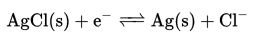
When an electrode is attached at the eye, this reaction reaches an equilibrium so that the electrode potential matches the potential at the skin. For an EOG, this potential is typically about a few millivolts. Another picture of a typical EOG signal is shown.
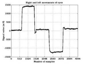
The voltage observed at the eye can be thought of as a very low-frequency AC signal (a DC with some drift due to instability of the electrodes), with some noise at a frequency of about 50 Hz.
It is significant to note that using electrodes to record presents a significant safety hazard. If a DC power supply is used improperly, a powerful driving force can cause this reaction can proceed to equilibrium in the opposite direction, so that the recording circuit influences the potential at the user’s eye. This can disrupt ion concentrations at the electrode interface and cause serious medical problems. Therefore a great deal of care must be taken to electrically isolate our entire system while recording from a user’s eyes.
Logical Overview
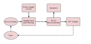
This block diagram shows an overview of the components necessary for our project. The raw EOG recording must go through extensive amplification and filtering to be converted into a voltage appropriate for processing in the PIC32. This is done with a multi-stage differential amplifier circuit, with power supply being provided by a battery circuit. The microcontroller records this value from an analog-to-digital converter and runs the game software, which has two outputs: the visual component of the game on an LCD display, and a sound output via a digital-to-analog converter that is sent to a speaker. The user reacts to the display while playing the game, which results in a change in the electrode signal that controls the game.
A picture of the game screen is shown below:
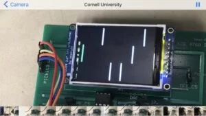
The user controls the paddle on the left, which switches between one of three locations when he or she looks left, right, or center. The bars move from the right side of the screen to the left at a constant velocity, and the user moves the paddle to avoid them.
Next to the paddle, three values are are printed to the screen. One is the score, which increments by 1 every time a bar is successfully avoided. The second is the value of the ADC, a useful tool for bug-checking, and the third is the time that the game has been running (in seconds). When the user does not successfully avoid an oncoming bar, the game ends and a “game over” message is displayed. The game also plays a sound every time a bar is avoided, and plays a different sound at game over.
Hardware Overview
As described earlier, the potential difference between the two eyes can be approximately 1-3 mV. With the appropriate ADC parameters, the PIC32 microcontroller board’s built-in ADC can only accept a voltage between 0 and 3.3 V. Therefore a significant portion of this project requires a high-gain amplification circuit that can measure the difference between the two eye inputs, filter out noise, and scale the potential to a magnitude appropriate for the ADC. In addition, electrical safety for such a project is paramount. Therefore the circuit must be completely electrically isolated from DC power supplies.
Shown below is a diagram of the complete circuit.
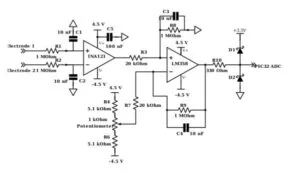
Our circuit has three important stages:
1) Differential amplifier stage: the two electrode signals are fed into a differential amplifier, an operational amplifier circuit that eliminates common components to the signal while amplifying the difference between them. This is the fundamental unit that allows for this comparison between eye voltage signals.
2) Balanced subtractor stage: this circuit amplifies the output of the differential amplifier, for a total gain to produce a voltage range appropriate for the ADC. In addition, the output of the differential amplifier is centered at an arbitrary DC offset and swings between positive and negative voltages, whereas the ADC requires an input between 0 and 3.3 V. This stage uses a manually set voltage offset input to center the signal produced by the differential amplifier at about 1.6 V.
3) Power supply stage: This circuit uses a 9 V battery and a unity-gain operational amplifier to establish a power line at 4.5 V, a ground line at 0, and a -Vdd line at -4.5 V. This configuration is used to power the two stages above.
Software Overview
Protothreads
The code for this lab was all written in C and programmed onto the PIC32. In order to develop robust and efficient code, we heavily relied upon Protothreads, written by Adam Dunkels. Protothreads is an open source library for C that implements a lightweight, stackless threading system to organize concurrent processes running in software. Such a library allows us to organize our software into different processes and functions, without having to worry about implementing details of scheduling and memory management. For more information on Protothreads and to download the library, visit Adam Dunkels’ page:
http://dunkels.com/adam/pt/index.html
Oscilloscope Design
Due to safety concerns, we cannot use an oscilloscope to test voltage signals while someone is using the project. Therefore we developed our own implementation of an oscilloscope on the TFT LCD screen. This code configures the ADC and continuously samples the ADC value at a frequency of 125 Hz, displaying two seconds of the amplified input signal across the width of the screen. The height of the screen represents the range of the ADC (between 0 and 3.3 volts). A picture of an example recording is shown below, using a sinusoidal input from a function generator.
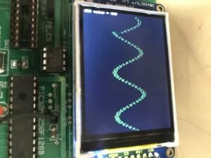
The implementation is fairly simple and only relies on one continuously running thread, which after setup reads the ADC value and performs a print to the TFT display on every iteration.
Game Software
Our game implementation uses three threads:
1) A timer thread. This thread runs once a second, incrementing the system timer that counts the game time and refreshing the values that are printed to the screen. It also prints the game over screen when the condition is enabled, and plays the game over sound.
2) A controller thread: This thread runs every 8 milliseconds and reads the ADC value to determine the new position of the paddle.
3) A dynamics thread: This thread stores information about the approaching obstacles, spawning them from the right side of the screen and updating their locations every iteration. It also detects collisions, updating the score when the user successfully avoids an obstacle or initiating game over.
Prior to scheduling, the game code also performs necessary setup for the ADC, SPI to interface between the DAC and the PIC32, DMA to generate sounds, and initiation functions to set up ProtoThreads for the above processes.
Design Standards
A set of standards for electrooculography is given by the ISCEV – the International Society for Clinical Electrophysiology of Vision. A paper describing these standards is given here:
https://www.ncbi.nlm.nih.gov/pmc/articles/PMC1820752/
Pupils: Apply dilating drops to the user’s pupils before beginning recording.
Electrodes: After suitable skin preparation, place small recording electrodes, close to the canthi of each eye. Connect the electrodes from each eye to separate channels of a differential amplifier. The ‘ground’ electrode can be placed on the forehead.
Amplifier: This should have a band pass of either 0 (DC) to 30 Hz, or 0.1 to 30 Hz, to provide recordings of the saccades which appear as square waves.
Pre-preparation: The test subject should be in stable indoor lighting for as long as possible before the test, and should not be exposed to any large changes in lighting (lighter/darker) during this period, such as indirect ophthalmoscopy. As near as is practical, the pre-test light exposure should be the same for all test subjects.
Preparing the test subject: Explain the procedure including, ‘chin/head on rest/restraint in stimulator, 15 min dark, 15 min light, fixation lights alternate in simple rhythmic manner, for 10 s each minute, when lights change, move eyes in single sweep to next one, do not turn head, do not anticipate the changes’. Practice the procedure with the recording system on and coach the subject if there is head movement, overshoot, stepping, or anticipation.
Measure the amplitude of the EOG: Taking care to remove the effects of overshoot and stepped saccades, measure the EOG amplitude in μV, either manually or by a computer algorithm. Calculate the average of the amplitudes in each 10 s trial.
Some of these standards are highly specific to medical applications of EOG recording and are meant to obtain accurate recordings for diagnosis. These aspects of the proposed standards are not completely relevant to our particular project, as we base our control of the game on thresholds in the amplified voltage signal so we do not need to be entirely accurate. However, safety concerns are still of utmost importance.
We did not use dilating drops before recording, but we adhered fairly well to the other standards. Our electrode arrangement was exactly as specified, using a ground electrode on the forehead. We did not use a bandpass filter, but we did use a low-pass filter that approximately fell on the range specified. The lab environment provided a very stable lighting source, and we made sure to coach our user and make instructions clear during calibration and before beginning the game. Our circuit contained several mechanisms to avoid overshooting such as our Schottky diode system.
Design
Hardware Design
Differential Amplifier Stage
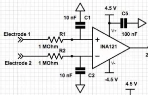
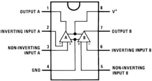
The main component of our differential amplifier stage is the Texas Instruments INA121, a differential amplifier integrated circuit. The purpose of a differential amplifier is to amplify the difference between two voltage inputs, while eliminating the common component between them. We chose the INA121 because it is cheap and has a very high common mode rejection ratio (the amount by which the amplifier attenuates the common signal between inputs – about 100 dB at a gain of 100) without any substantial efficiency drawbacks. A data sheet can be found here:
Here is a pin diagram for the circuit. Pins 7 and 4, the V+ and V- pins, are connected to +4.5 V and – 4.5 V as provided by our battery circuit (to be shown in more detail later) to power the amplifier. Pin 5, the reference, is connected to ground. Rg, connected between pins 1 and 8, is a gain resistor whose value determines the gain between the differential input and the amp’s output. Pins 2 and 3 are connected to our electrode inputs.
Before the connection to the amplifier input, the two electrode signals are connected to two low-pass filters (given by R1/C1 and R2/C2). The time constant for this filter is given by:
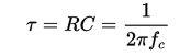
Here, the time constant is 0.01 seconds, and the cutoff frequency fc is 15.9 Hz. As discussed earlier, the electrode signals contain noise at approximately 50 Hz. This noise is also not necessarily attenuated by the differential amplifier, as it is random rather than coupled between the two electrodes. These filters are necessary to remove such noise at the input, while passing the essential DC component that results from the difference in eye position between the two recordings. These recordings will also have a frequency component when the user moves his or her eyes. However, the game does not require eye movement frequency as high as 16 Hz (nor is this easy), so this filter value is appropriate for eliminating noise while passing all the necessary signals to operate the game.
We chose an Rg value of 2.8 kΩ, for a differential gain of 17.7. The gain equation for the circuit is shown above:

This gain is not nearly enough to amplify the signal on its own (a 2 mV difference will yield an output of only ~35 mV). However, the amplifier becomes less stable when smaller resistors are used for much higher gain. We will use the second stage of the circuit to increase the gain.
An additional note – the 4.5 V power input to the INA121 is also connected to ground via a 100 nF capacitor. This is to reduce high-frequency noise from our battery power supply, which prior to this addition was shown to be slightly unstable.
Balanced Subtractor Stage
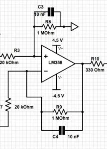
The balanced subtractor stage has two purposes. First, it provides a second voltage gain to further amplify the signal from the first stage. However, having just an operational amplifier for high gain at the second stage would not be appropriate.
The first stage amplifies a difference between the electrode inputs in both DC and AC components. This gain will be the same for both signal types, but the original signal’s magnitude may not be. It is expected that the DC difference between the eyes when holding still will be greater than the AC component that results from moving one’s eyes. Assuming 20 mV offset and 1 mVpp swing from the eyes, the expected output from the two stages will be 20V offset with 1Vpp (1000x gain). This is too high to be captured by the ADC, which can only read values from 0 – 3.3V. The second purpose of the balanced subtractor is to use a manual DC voltage offset value to negate the high gain that would appear in the DC offset and cause railing, while maintaining the high AC gain. Specifically, we will manually set the Voffset to a value that changes the DC component at the output so that both the DC and AC signals satisfy the range of the ADC. For example, if the output of the first stage amplifier was 400 mV offset with 20 mVpp swing (20x gain), the offset would need to be set slightly above 400 mV. Note that the offset should not fully cancel out the offset, since the voltage swing going into the ADC must be positive at all times (ADC can only capture positive values).
The primary component of the second circuit stage is a Texas Instruments LM358 operational amplifier. The data sheet can be found here:
Our non-inverting input at pin 3 is the amplified output from the INA121 (wired through a 20 kΩ resistor). The inverting input is the DC voltage offset, which we created using a potentiometer (described below). The amplifier is powered by +4.5 V and -4.5 V.
Two more filters are connected at each input with the same time constant calculated earlier of 0.01 seconds. These should be included again because, while 50 Hz noise was attenuated by the first set of filters, the differential amplifier stage can also amplify this noise after attenuation. The second set of filters provides another stage of attenuation for higher frequency noise, negating any amplification effects from the first stage.
In addition to providing filtering, the 1 MOhm resistor connecting the output and inverting input is necessary to provide gain for the amplifier. The gain formula is given as:

Z|| is the 1 MOhm resistor in parallel with the capacitor, and R is the 20 kOhm resistor at the inverting input. The expected gain of this amplifying stage is 50, making the total gain across both stages 885.
The value of Voffset was determined manually using a potentiometer. We used the following voltage divider circuit to produce a variable voltage appropriate for the amplifier:
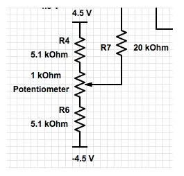
Changing the value of the potentiometer will change the value of the offset according to the variable resistance value. The offset at the output can be determined by the following equation:
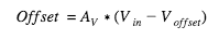
Recall that AV = 50 (approximately). The desired output of the second stage is 1650 mV (halfway between 0 and 3.3 volts, the range of the ADC). The output DC component is effectively the difference between the input signal and the manual offset, scaled by the gain of the amplifier. Given the gain of the second stage, the desired offset should be 33mV + offset from first stage. Again, assuming that the input of the second stage is 400 mV offset with 20 mVpp swing, the desired offset should be +/- 433mV exactly. The next step after determining this range of expected values is to create a voltage divider so that the potentiometer can be used to produce a voltage at approximately the same range of values.
The voltage drop across the potentiometer in a voltage divider is given as Vapplied*Rpot/Rtotal ,where Vapplied = 9V. For our divider, we set our 1 kΩ potentiometer in series with two 5.1 kΩ resistors to reach a offset swing of +/- 450 mV. Below shows the two equations used to calculate the maximum and minimum swings for the offset.
Source: EOG-Controlled Video Game
- How does the user control the game?
The user moves their eyes left or right to change the position of the paddle on the LCD screen. - What type of electrodes are used in this project?
Silver-plated electrodes are used to record the EOG signal from both eyes. - Why was EOG chosen over EEG for this project?
EOG is easier to record because the potential is closer to the surface and presents fewer safety hazards than scalp recording. - Does the system use an oscilloscope for testing?
No, an oscilloscope cannot be used due to safety concerns; instead, an oscilloscope design was implemented on the TFT LCD screen. - What is the total gain of the amplification circuit?
The total gain across both stages is approximately 885. - How is the DC offset managed in the second stage?
A manually set voltage offset using a potentiometer centers the signal at about 1.6 V to fit the ADC range. - What software library organizes the concurrent processes?
The code relies on Protothreads, a lightweight stackless threading system written in C. - Does the game play any sounds?
Yes, the game plays a sound every time a bar is avoided and a different sound when the game ends.